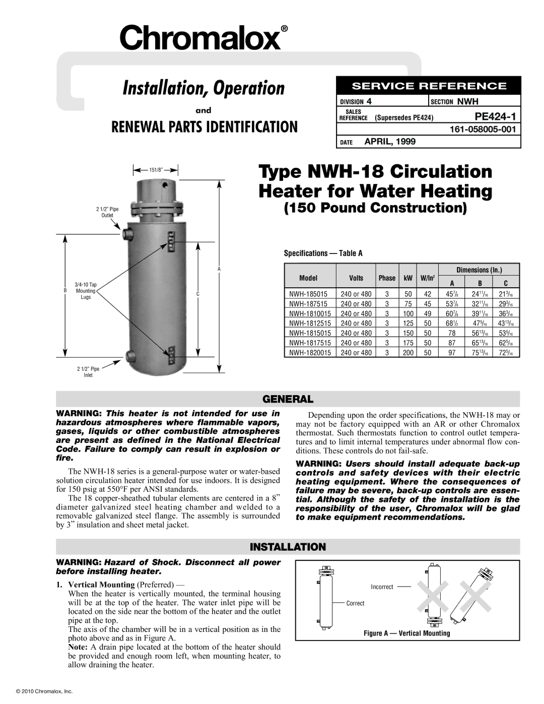
NWH-185015 specifications
The Chromalox NWH-185015 is a versatile and efficient electric heating solution designed to meet a variety of industrial and commercial heating applications. This product stands out due to its robust construction, extensive features, and the innovative technologies that enhance its performance.One of the key features of the NWH-185015 is its powerful heating capacity. With a wattage rating of 15,000 watts, it is capable of delivering substantial thermal energy, making it suitable for tasks that require rapid heating or maintaining precise temperature levels. The unit is designed for use in applications such as water heating, process heating, and even for providing comfort heating in specific environments.
The NWH-185015 utilizes advanced heating technologies to ensure efficient energy usage while minimizing operational costs. It incorporates a thermostat control system that allows for precise temperature regulation. The built-in safety features include over-temperature protection and a high limit cutoff switch, ensuring reliable operation without compromising safety.
Another major characteristic of this unit is its durable design. Constructed with high-quality materials, the NWH-185015 is built to withstand harsh environments and demanding operating conditions. This durability not only extends the unit's lifespan but also reduces maintenance costs over time.
Installation and integration of the NWH-185015 into existing systems are streamlined, thanks to its user-friendly design. It offers multiple configurations and voltage options, making it adaptable to a range of applications. Moreover, its compact size allows for easy placement in various settings, whether in tight spaces or established infrastructures.
The NWH-185015 also emphasizes energy efficiency, which is increasingly important in today's energy-conscious market. By utilizing intelligent heating elements and smart controls, the unit helps minimize energy consumption without sacrificing performance.
In summary, the Chromalox NWH-185015 is a top-tier solution for anyone seeking reliable electric heating. Its powerful output, innovative technologies, and robust construction combine to deliver outstanding performance across a multitude of applications. Whether for industrial processes or commercial needs, this heating unit offers the reliability and efficiency essential for modern heating demands.

