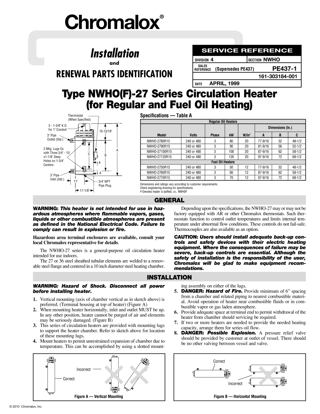
NWHO(F)-27 specifications
The Chromalox NWHO(F)-27 is a state-of-the-art industrial heating solution that offers exceptional performance in various applications. Designed for versatility and efficiency, this product is ideal for processes requiring precise temperature control and uniform heating. With its robust construction and innovative technology, the NWHO(F)-27 has gained reputation in industries such as chemical processing, food production, and pharmaceuticals.One of the most significant features of the NWHO(F)-27 is its advanced heating technology. The unit utilizes a high-quality heating element that ensures consistent and reliable temperature output. This technology minimizes hot spots and ensures even heat distribution across the entire surface area, which is crucial for processes that demand precise thermal management. The integration of advanced thermal sensors also enables real-time monitoring and automated adjustments, enhancing energy efficiency and reducing operational costs.
The NWHO(F)-27 is designed with user-friendly controls that allow operators to set and adjust temperature parameters easily. Its intuitive digital interface ensures that users can monitor temperature, system status, and other essential metrics at a glance. This aspect of the design is particularly beneficial in settings where quick adjustments are necessary to maintain process integrity.
Durability is another key characteristic of the Chromalox NWHO(F)-27. Constructed from high-strength materials, this heating unit is built to withstand harsh operating environments. It is resistant to corrosion and capable of withstanding high temperatures, ensuring long-lasting performance and reliability. The unit's compact design also makes it easy to integrate into existing systems without requiring significant modifications.
Energy efficiency is a priority in the design of the NWHO(F)-27. With its innovative heating technology, the unit significantly reduces energy consumption compared to conventional heating systems. This not only lowers operational costs but also minimizes the environmental impact, making it an excellent choice for companies striving for sustainability.
In summary, the Chromalox NWHO(F)-27 stands out for its advanced heating technology, user-friendly controls, durability, and energy efficiency. Whether for industrial applications or specialized processes, this heating solution provides the reliability and performance needed to meet the demands of modern production environments. Its thoughtful engineering and robust design make it an asset for companies seeking to enhance their heating capabilities while maintaining high standards of quality and efficiency.