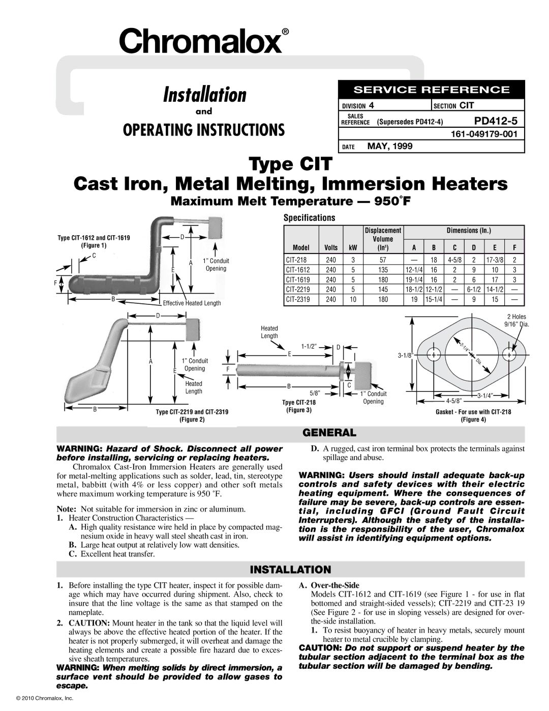
PD412-5 specifications
The Chromalox PD412-5 is a cutting-edge temperature control solution renowned for its advanced features and reliable performance. Designed for industrial heating applications, the PD412-5 is characterized by its high efficiency, versatility, and precise control capabilities.One of the standout features of the PD412-5 is its powerful heating capacity. With a robust output, this model can quickly and efficiently heat fluids, gases, and surfaces, making it suitable for various applications ranging from manufacturing processes to laboratory environments. The PD412-5 can handle high-temperature settings while maintaining stability, ensuring consistent performance across different operational conditions.
Another key characteristic is the integrated digital controller, which allows users to easily set and monitor temperatures. The intuitive interface provides real-time feedback, enabling operators to adjust parameters quickly based on process requirements. This digital technology not only enhances user convenience but also improves accuracy, resulting in reduced energy consumption and lower operational costs.
In terms of construction, the PD412-5 is built with high-quality materials to ensure durability and longevity. The unit is designed to withstand harsh environments and offers protection against corrosion, making it an excellent choice for industries like chemical processing, food production, and pharmaceuticals. Its robust design minimizes maintenance needs, further contributing to its efficiency.
The PD412-5 is also compatible with various control systems and can be integrated into existing setups with ease. Its modular design allows for seamless scalability, making it an ideal choice for both small-scale operations and large industrial installations. Flexibility in installation options ensures that the PD412-5 can be adapted to diverse heating configurations.
Safety is a top priority in the design of the PD412-5. The unit features multiple safety mechanisms, including over-temperature protection and alarms, to safeguard both the equipment and the surrounding environment. This commitment to safety makes it a reliable choice for critical applications.
In summary, the Chromalox PD412-5 is an advanced temperature control solution that combines powerful heating capabilities with precision control, robust construction, and user-friendly technology. Its adaptability, safety features, and efficiency make it a valuable asset for industrial heating applications, ensuring it stands out in a competitive market.