INSTALLATION
ELECTRIC SHOCK HAZARD. Disconnect all power before installing heater. Failure to do so could result in personal injury or property damage. Heater must be installed by a qualified person in accordance with the National Electrical Code. NFPA 70.
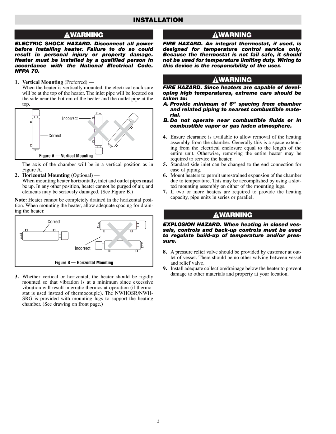
1.Vertical Mounting (Preferred) —
When the heater is vertically mounted, the electrical enclosure will be at the top of the heater. The inlet pipe will be located on the side near the bottom of the heater and the outlet pipe at the top.
Incorrect ![]()
![]()
Correct
Figure A — Vertical Mounting
The axis of the chamber will be in a vertical position as in Figure A.
2.Horizontal Mounting (Optional) —
When mounting heater horizontally, inlet and outlet pipes must be up. In any other position, heater cannot be purged of air, and elements may be seriously damaged. (See Figure B.)
Note: Heater cannot be completely drained in the horizontal posi- tion. When mounting the heater, allow adequate spacing for drain- ing the heater.
Correct
Incorrect
Figure B — Horizontal Mounting
3.Whether vertical or horizontal, the heater should be rigidly mounted so that vibration is at a minimum since excessive vibration will result in erratic thermostat operation (if thermo- stat is used instead of thermocouple). The NWHOSR/NWH- SRG is provided with mounting lugs to support the heating chamber. (See drawing on front page.)
FIRE HAZARD. An integral thermostat, if used, is designed for temperature control service only. Because the thermostat is not fail safe, it should not be used for temperature limiting duty. Wiring to this device is the responsibility of the user.
FIRE HAZARD. Since heaters are capable of devel- oping high temperatures, extreme care should be taken to:
A. Provide minimum of 6” spacing from chamber and related piping to nearest combustible mate- rial.
B. Do not operate near combustible fluids or in combustible vapor or gas laden atmosphere.
4.Ensure clearance is available to allow removal of the heating assembly from the chamber. Generally this is a space extend- ing from the electrical enclosure equal to the length of the entire unit. Otherwise, removing the entire heater may be required to service the heater.
5.Standard side inlet can be changed to the end connection for ease of piping.
6.Mount heaters to permit unrestrained expansion of the chamber due to temperature. This may be accomplished by using a slot- ted mounting assembly on either of the mounting lugs.
7.If two or more heaters are required to provide the heating capacity, pipe units in series or parallel.
EXPLOSION HAZARD. When heating in closed ves- sels, controls and
8.A pressure relief valve should be provided by customer at out- let of vessel. There should be no other valving between vessel and relief valve.
9.Install adequate collection/drainage below the heater to prevent damage to other materials and property at your location.
2