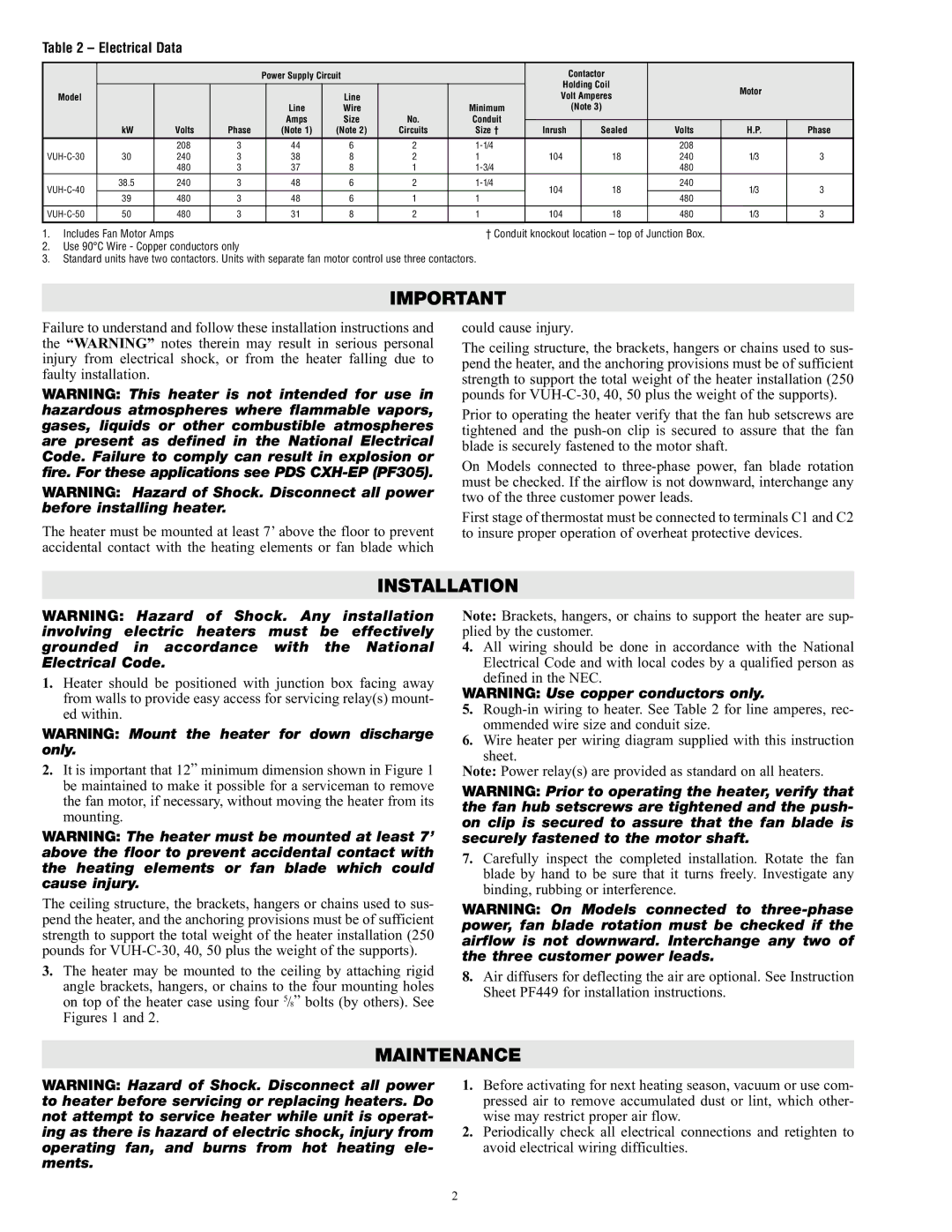
Table 2 – Electrical Data


Power Supply Circuit


Contactor


Holding Coil


Motor


Model


Line


Volt Amperes


Line

Wire


Minimum


(Note 3)


Amps

Size

No.

Conduit


kW


Volts

Phase

(Note 1)

(Note 2)

Circuits

Size †

Inrush


Sealed

Volts

H.P.

Phase


208

3

44

6

2

1-1/4


208


VUH-C-30

30


240

3

38

8

2

1

104


18

240

1/3

3


480

3

37

8

1

1-3/4


480


VUH-C-40

38.5


240

3

48

6

2

1-1/4

104


18

240

1/3

3


39


480

3

48

6

1

1


480


VUH-C-50

50


480

3

31

8

2

1

104


18

480

1/3

3


1. Includes Fan Motor Amps


† Conduit knockout location – top of Junction Box.


2.Use 90°C Wire - Copper conductors only

3.Standard units have two contactors. Units with separate fan motor control use three contactors.

IMPORTANT

Failure to understand and follow these installation instructions and the “WARNING” notes therein may result in serious personal injury from electrical shock, or from the heater falling due to faulty installation.

WARNING: This heater is not intended for use in hazardous atmospheres where flammable vapors, gases, liquids or other combustible atmospheres are present as defined in the National Electrical Code. Failure to comply can result in explosion or fire. For these applications see PDS CXH-EP (PF305).

WARNING: Hazard of Shock. Disconnect all power before installing heater.

The heater must be mounted at least 7’ above the floor to prevent accidental contact with the heating elements or fan blade which

could cause injury.

The ceiling structure, the brackets, hangers or chains used to sus- pend the heater, and the anchoring provisions must be of sufficient strength to support the total weight of the heater installation (250 pounds for VUH-C-30, 40, 50 plus the weight of the supports).

Prior to operating the heater verify that the fan hub setscrews are tightened and the push-on clip is secured to assure that the fan blade is securely fastened to the motor shaft.

On Models connected to three-phase power, fan blade rotation must be checked. If the airflow is not downward, interchange any two of the three customer power leads.

First stage of thermostat must be connected to terminals C1 and C2 to insure proper operation of overheat protective devices.

INSTALLATION

WARNING: Hazard of Shock. Any installation involving electric heaters must be effectively grounded in accordance with the National Electrical Code.

1.Heater should be positioned with junction box facing away from walls to provide easy access for servicing relay(s) mount- ed within.

WARNING: Mount the heater for down discharge only.

2.It is important that 12” minimum dimension shown in Figure 1 be maintained to make it possible for a serviceman to remove the fan motor, if necessary, without moving the heater from its mounting.

WARNING: The heater must be mounted at least 7’ above the floor to prevent accidental contact with the heating elements or fan blade which could cause injury.

The ceiling structure, the brackets, hangers or chains used to sus- pend the heater, and the anchoring provisions must be of sufficient strength to support the total weight of the heater installation (250 pounds for VUH-C-30, 40, 50 plus the weight of the supports).

3.The heater may be mounted to the ceiling by attaching rigid angle brackets, hangers, or chains to the four mounting holes on top of the heater case using four 5/8” bolts (by others). See Figures 1 and 2.

Note: Brackets, hangers, or chains to support the heater are sup- plied by the customer.

4.All wiring should be done in accordance with the National Electrical Code and with local codes by a qualified person as defined in the NEC.

WARNING: Use copper conductors only.

5.Rough-in wiring to heater. See Table 2 for line amperes, rec- ommended wire size and conduit size.

6.Wire heater per wiring diagram supplied with this instruction sheet.

Note: Power relay(s) are provided as standard on all heaters.

WARNING: Prior to operating the heater, verify that the fan hub setscrews are tightened and the push- on clip is secured to assure that the fan blade is securely fastened to the motor shaft.

7.Carefully inspect the completed installation. Rotate the fan blade by hand to be sure that it turns freely. Investigate any binding, rubbing or interference.

WARNING: On Models connected to three-phase power, fan blade rotation must be checked if the airflow is not downward. Interchange any two of the three customer power leads.

8.Air diffusers for deflecting the air are optional. See Instruction Sheet PF449 for installation instructions.

MAINTENANCE

WARNING: Hazard of Shock. Disconnect all power to heater before servicing or replacing heaters. Do not attempt to service heater while unit is operat- ing as there is hazard of electric shock, injury from operating fan, and burns from hot heating ele- ments.

1.Before activating for next heating season, vacuum or use com- pressed air to remove accumulated dust or lint, which other- wise may restrict proper air flow.

2.Periodically check all electrical connections and retighten to avoid electrical wiring difficulties.

2

Page 2
Image 2
Chromalox PF452-4 specifications Installation, Maintenance

PF452-4 specifications

The Chromalox PF452-4 is a state-of-the-art temperature control unit designed for precise heating applications in various industrial settings. Known for its reliability and efficiency, this model stands out in the market, meeting the needs of professionals across multiple sectors, including manufacturing, food processing, and pharmaceuticals.

One of the primary features of the PF452-4 is its robust construction, which ensures durability in demanding environments. The unit is built with high-quality materials that withstand extreme temperatures and resist corrosion, allowing for prolonged usage without degradation in performance. The design is also compact, making it easy to install in tight spaces while still providing sufficient heating capacity.

The PF452-4 utilizes advanced digital control technology, enabling users to achieve accurate temperature settings with ease. Its user-friendly interface includes a digital display that provides real-time temperature readings, allowing for quick adjustments as needed. The control system also features programmable settings, giving operators the flexibility to set heating schedules based on specific operational requirements.

Another significant characteristic of the Chromalox PF452-4 is its energy efficiency. By utilizing intelligent heating technology, the unit minimizes energy usage while maximizing output, which translates into reduced operational costs for businesses. This efficiency is not just beneficial for the environment; it also contributes to a lower carbon footprint.

Safety is paramount in any industrial application, and the PF452-4 does not fall short in this aspect. Equipped with over-temperature protection, as well as safety cut-off mechanisms, the unit ensures safe operation even in critical processes. These safety features offer peace of mind to operators, allowing them to focus on their tasks without worrying about overheating hazards.

Furthermore, the PF452-4 is compatible with various heating media, including water and oil, making it versatile for different applications. Its broad temperature range accommodates diverse operational requirements, from low to high-temperature processes.

In conclusion, the Chromalox PF452-4 is an exemplary heating solution that combines reliability, efficiency, and safety. With its advanced features, robust design, and energy-saving capabilities, it is a valuable addition to any industrial heating application. This unit not only meets but often exceeds the expectations of operators, solidifying its position as a leader in temperature control technology.