
PG417-3 specifications
The Chromalox PG417-3 is a highly regarded industrial heating solution that combines advanced technologies with robust engineering to meet the diverse needs of various applications. Known for its efficiency and reliability, the PG417-3 is designed to provide precise temperature control in both heating and process applications.One of the standout features of the PG417-3 is its powerful heating capacity. With a maximum wattage output, this unit is capable of heating large volumes of fluids or materials quickly and efficiently. This capability makes it particularly suitable for industrial environments where downtime can be costly, and rapid heating is essential for operational continuity.
The PG417-3 utilizes advanced control technologies that enhance its performance. It is equipped with microprocessor-based controls that allow for accurate temperature monitoring and regulation. These controls enable the user to set desired temperature profiles, ensuring that processes maintain the required thermal conditions. The integrated safety features, such as over-temperature protection and alarms, further enhance the device's reliability, ensuring safe operation in demanding environments.
Another significant characteristic of the Chromalox PG417-3 is its robust construction. It is designed to withstand extreme temperatures and harsh environmental conditions commonly found in industrial settings. The materials used in its construction are selected for durability and resistance to corrosion and wear, providing longevity and minimizing maintenance needs.
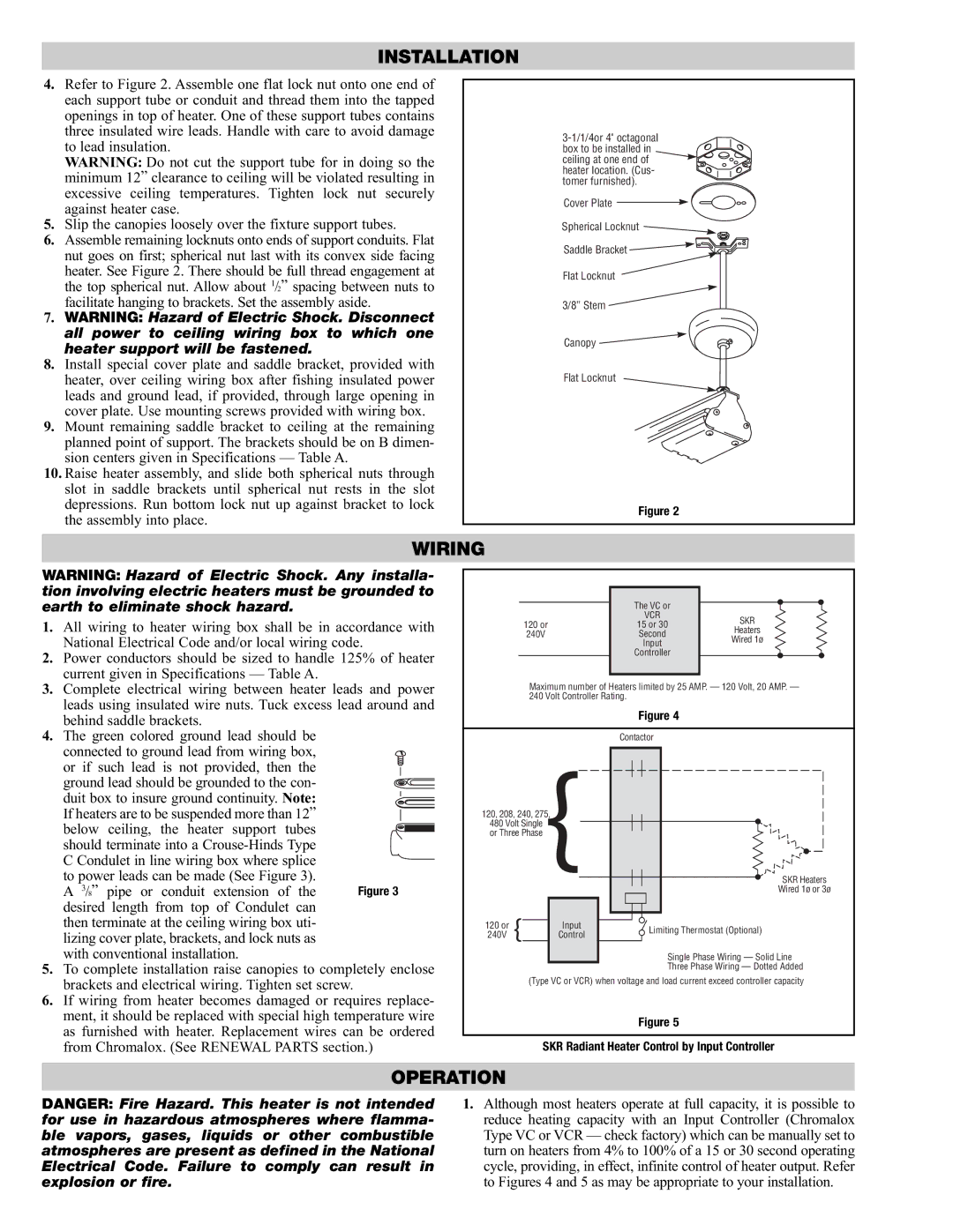
In addition, the PG417-3 is designed with adaptability in mind. It can be easily integrated into existing systems and offers various installation options to accommodate different layouts and requirements. Its versatility makes it suitable for applications ranging from chemical processing to food production, where precise heating is critical.
The energy efficiency of the PG417-3 is another highlight, contributing to reduced operational costs and environmental impact. By optimizing energy use, this heater not only saves money for users but also aligns with sustainable practices that many industries are striving to achieve.
In conclusion, the Chromalox PG417-3 embodies a combination of power, precision, and durability, making it an optimal choice for industrial heating applications. Its advanced technologies, robust construction, and energy-efficient design ensure that it meets the rigorous demands of modern processing environments while offering reliability and ease of use.