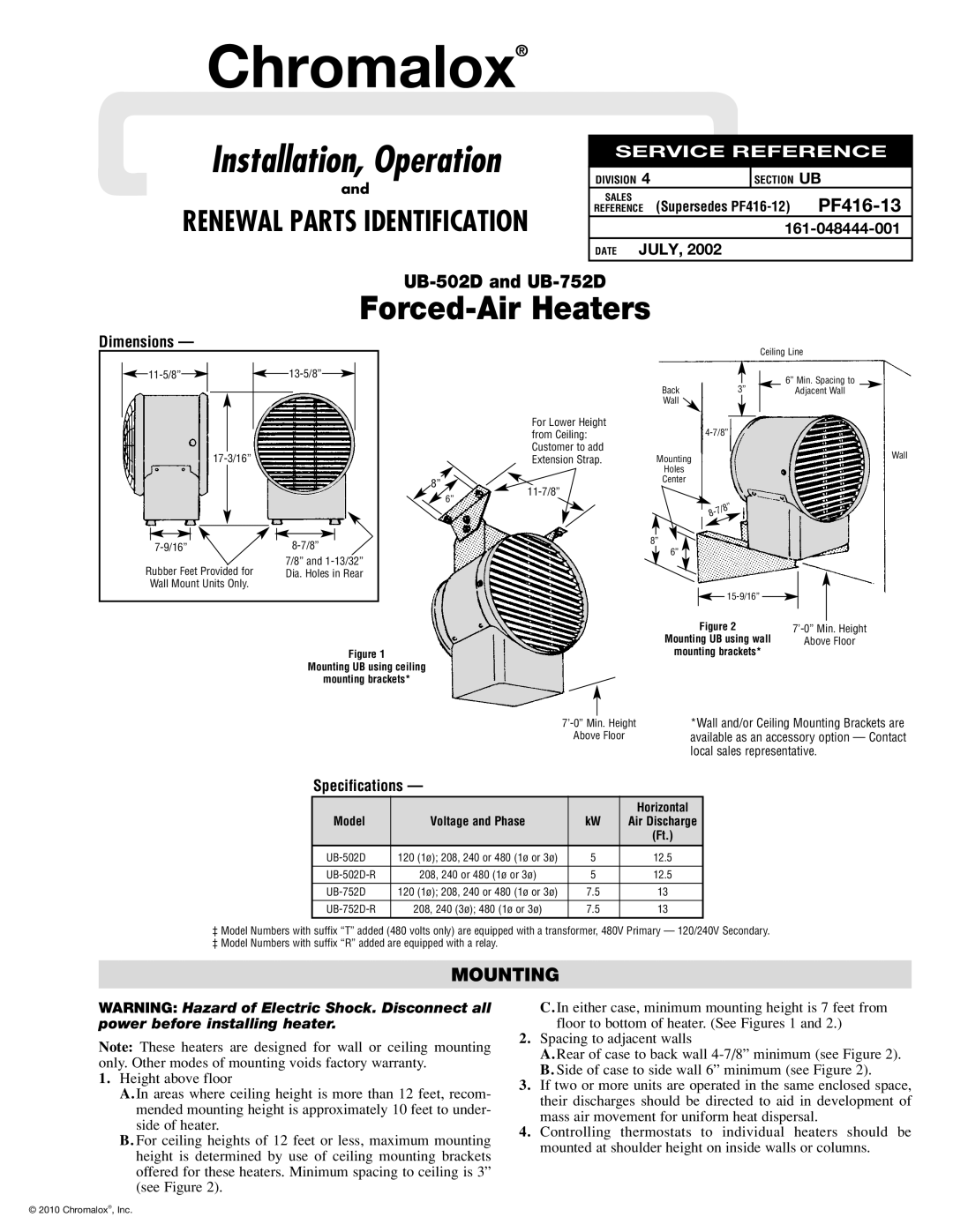
UB-752D, UB-502D specifications
The Chromalox UB-502D and UB-752D are advanced electronic temperature control units designed for precise temperature management in various industrial applications. These units excel in providing reliable and efficient heating solutions, making them suitable for diverse environments such as manufacturing facilities, laboratories, and testing centers.One of the standout features of the UB-502D and UB-752D is their dual-output capability, rendering them capable of controlling two separate heating zones independently. This is particularly advantageous in processes requiring different temperature settings, allowing for greater flexibility and efficiency in operations. Each unit is equipped with a digital display and user-friendly interface, facilitating easy navigation and real-time monitoring of temperature settings.
The UB-502D and UB-752D utilize advanced PID (Proportional-Integral-Derivative) control technology. This sophisticated control algorithm continuously adjusts the heating output, ensuring temperatures remain stable and within the desired range. This level of precision enhances process reliability and contributes to improved product quality, which is essential in industries where temperature control is critical.
Both models incorporate a wide temperature control range, making them suitable for various applications. The UB-502D can regulate temperatures up to 500°F, while the UB-752D extends this capability to 750°F, catering to high-temperature requirements. This versatility allows them to accommodate a range of heating applications, from material processing to equipment heating.
Another significant aspect is the robust construction of these units, designed to withstand harsh industrial conditions. The durable housing not only ensures longevity but also contributes to safety, safeguarding against potential hazards associated with overheating or equipment failures. Moreover, the units are designed with built-in safety features like over-temperature protection and alarms, providing an extra layer of security in operational settings.
The Chromalox UB-502D and UB-752D also offer options for remote monitoring and control, allowing operators to manage temperature settings from a distance. This connectivity is increasingly important in modern industrial environments where real-time data and remote access can enhance operational efficiency and responsiveness.
In conclusion, the Chromalox UB-502D and UB-752D are state-of-the-art electronic temperature control units that combine precision, flexibility, and safety. Their advanced technologies, robust design, and user-friendly interfaces make them indispensable tools for any industrial application requiring reliable temperature management. Whether for manufacturing processes or laboratory experiments, these units set a standard for performance and efficiency in temperature control solutions.

