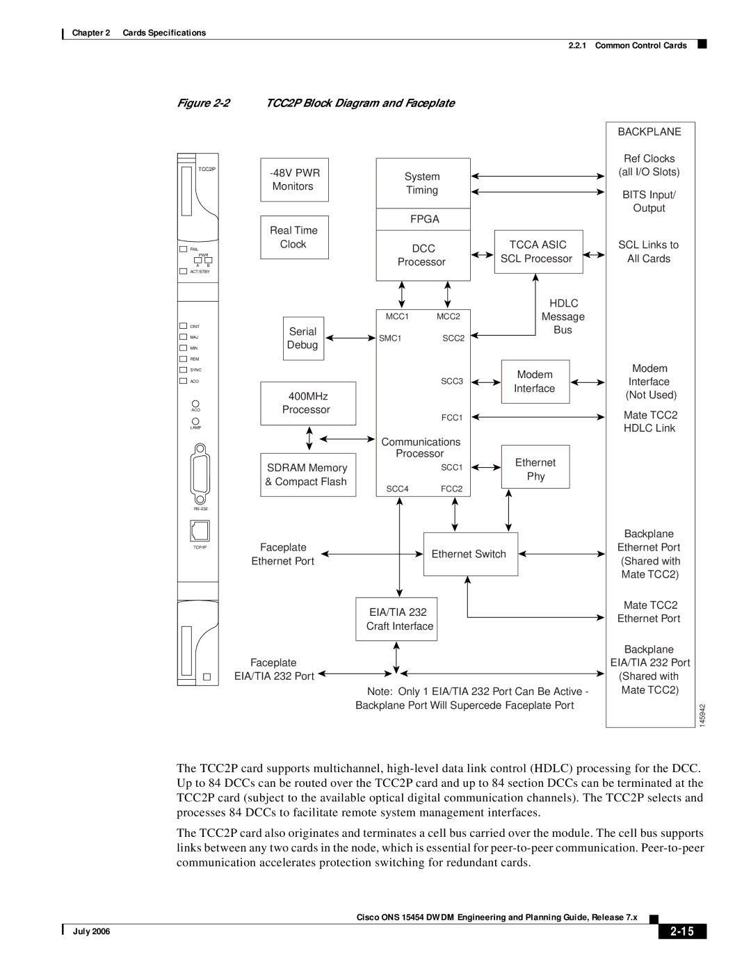
15454 specifications
Cisco Systems' 15454 is a leading optical networking platform designed to address a range of connectivity needs for service providers, enterprises, and data centers. As part of the Cisco ONS (Optical Networking System) portfolio, the 15454 provides advanced capabilities that cater to the evolving demands of high-performance network requirements.At its core, the Cisco 15454 is built for scalability and versatility. It supports a variety of transmission methods, including SONET (Synchronous Optical Networking), SDH (Synchronous Digital Hierarchy), and WDM (Wavelength Division Multiplexing). This flexibility makes the platform ideal for deploying both legacy services and next-generation applications.
One of the standout features of the 15454 is its ability to support high-capacity wavelengths, allowing for greater bandwidth utilization across fiber networks. With advanced Dense Wavelength Division Multiplexing (DWDM) technology, the platform ensures efficient use of the available fiber and extends the distance over which data can be transmitted. This results in reduced operational costs while maximizing throughput.
The Cisco 15454 also comes equipped with an array of interfaces supported by its modular design. The platform can accommodate Ethernet, SONET/SDH, and IP services, which means it can seamlessly handle a wide range of protocols. The modular architecture allows network operators to tailor the system to their specific requirements, offering a variety of line cards and interfaces to choose from.
Another critical characteristic of the 15454 is its built-in protection mechanisms. The system offers diverse and automatic protection schemes such as optical Layer 1 protection, ensuring high availability and network resilience. This capability is essential for mission-critical applications where uptime is paramount.
Moreover, the platform is complemented by Cisco's sophisticated management solutions, which streamline the operational management of the network. With tools that provide in-depth monitoring and troubleshooting capabilities, network administrators can maintain optimal performance and quickly respond to any issues that may arise.
In summary, the Cisco Systems 15454 is a robust and adaptable optical networking solution. Its main features, including advanced DWDM capabilities, modular architecture, protocol versatility, and enhanced protection mechanisms, make it a preferred choice for organizations looking to scale their network infrastructure while ensuring high service reliability and performance. Whether for expanding bandwidth or modernizing legacy networks, the Cisco 15454 stands out as a powerful tool in the ever-evolving landscape of telecommunications.

