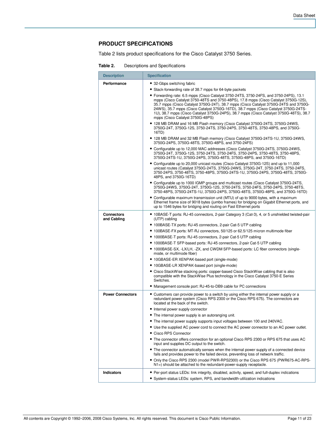
3750-48PS, 3750-24PS specifications
Cisco Systems has long been a leader in the networking industry, providing robust solutions that cater to diverse organizational needs. Among its array of products, the Cisco Catalyst 3750 series stands out, particularly the models 3750-24PS and 3750-48PS. These switches are designed for the enterprise market, delivering high performance, advanced features, and exceptional flexibility.The Cisco Catalyst 3750-24PS is a 24-port Ethernet switch that comes equipped with Power over Ethernet (PoE) capabilities, allowing it to supply power to connected devices such as IP phones and wireless access points. This model supports both Layer 2 and Layer 3 operations, providing a versatile solution suitable for various network topologies. The switch boasts a 2.5 Gbps stack bandwidth, enabling seamless integration into Cisco's StackWise technology. This feature allows multiple switches to be interconnected, functioning as a single unified system, which enhances network scalability and management.
On the other hand, the Cisco Catalyst 3750-48PS features 48 Ethernet ports with PoE support, making it an excellent choice for larger deployments. This model offers enhanced connectivity options and greater power capabilities, catering to more substantial device populations within enterprises. Like its 24-port counterpart, it supports VLANs, which facilitate traffic segregation for optimal network performance.
Both models support advanced Layer 3 routing protocols, including RIP, OSPF, and EIGRP, allowing for efficient routing within the network. The Quality of Service (QoS) capabilities ensure optimal delivery of time-sensitive applications, such as voice and video, providing a seamless user experience.
Another remarkable feature of the Cisco Catalyst 3750 series is the incorporation of Cisco's Smart Install technology, which simplifies switch deployment and management. This technology automates device configuration and software upgrades, reducing the operational burden on network administrators.
Security is a priority in today’s networking environment, and the 3750 series includes numerous security features. This encompasses features like dynamic ARP inspection, DHCP snooping, and port security, which work in concert to safeguard data integrity and access controls.
In summary, the Cisco Catalyst 3750-24PS and 3750-48PS are exceptional switches that deliver a blend of performance, flexibility, and security. Their advanced features make them suitable for both small and large enterprises, effectively meeting the demands of modern networking environments while ensuring scalability and manageability.

