Catalyst Wiring Closet Deployment Scenarios
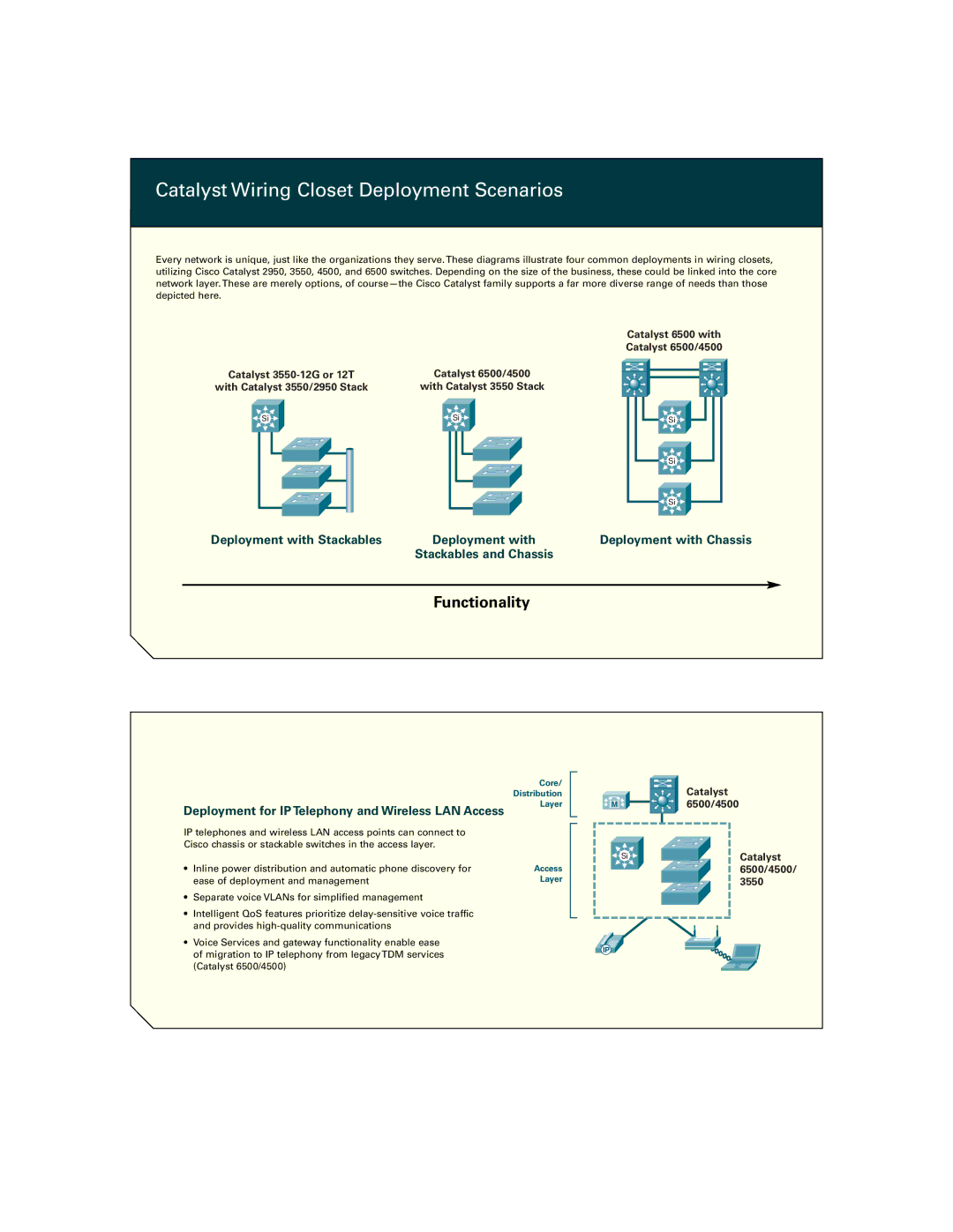
Every network is unique, just like the organizations they serve. These diagrams illustrate four common deployments in wiring closets, utilizing Cisco Catalyst 2950, 3550, 4500, and 6500 switches. Depending on the size of the business, these could be linked into the core network layer. These are merely options, of
Catalyst 6500 with
Catalyst 6500/4500
Catalyst | Catalyst 6500/4500 |
with Catalyst 3550/2950 Stack | with Catalyst 3550 Stack |
Si | Si |
![]()
![]() Si
Si ![]()
![]()
|
| Si |
|
| Si |
Deployment with Stackables | Deployment with | Deployment with Chassis |
| Stackables and Chassis |
|
Functionality
Deployment for IP Telephony and Wireless LAN Access
Core/
Distribution
Layer
| Catalyst |
M | 6500/4500 |
IP telephones and wireless LAN access points can connect to Cisco chassis or stackable switches in the access layer.
•Inline power distribution and automatic phone discovery for ease of deployment and management
•Separate voice VLANs for simplified management
•Intelligent QoS features prioritize
•Voice Services and gateway functionality enable ease of migration to IP telephony from legacy TDM services (Catalyst 6500/4500)
Access Layer
Si | Catalyst |
| 6500/4500/ |
| 3550 |
IP