Standards Compliance
Se n d d o c u m e n t a t i o n c o m m e n t s t o m d s f e e d b a ck - d o c @ c i s c o . c o m
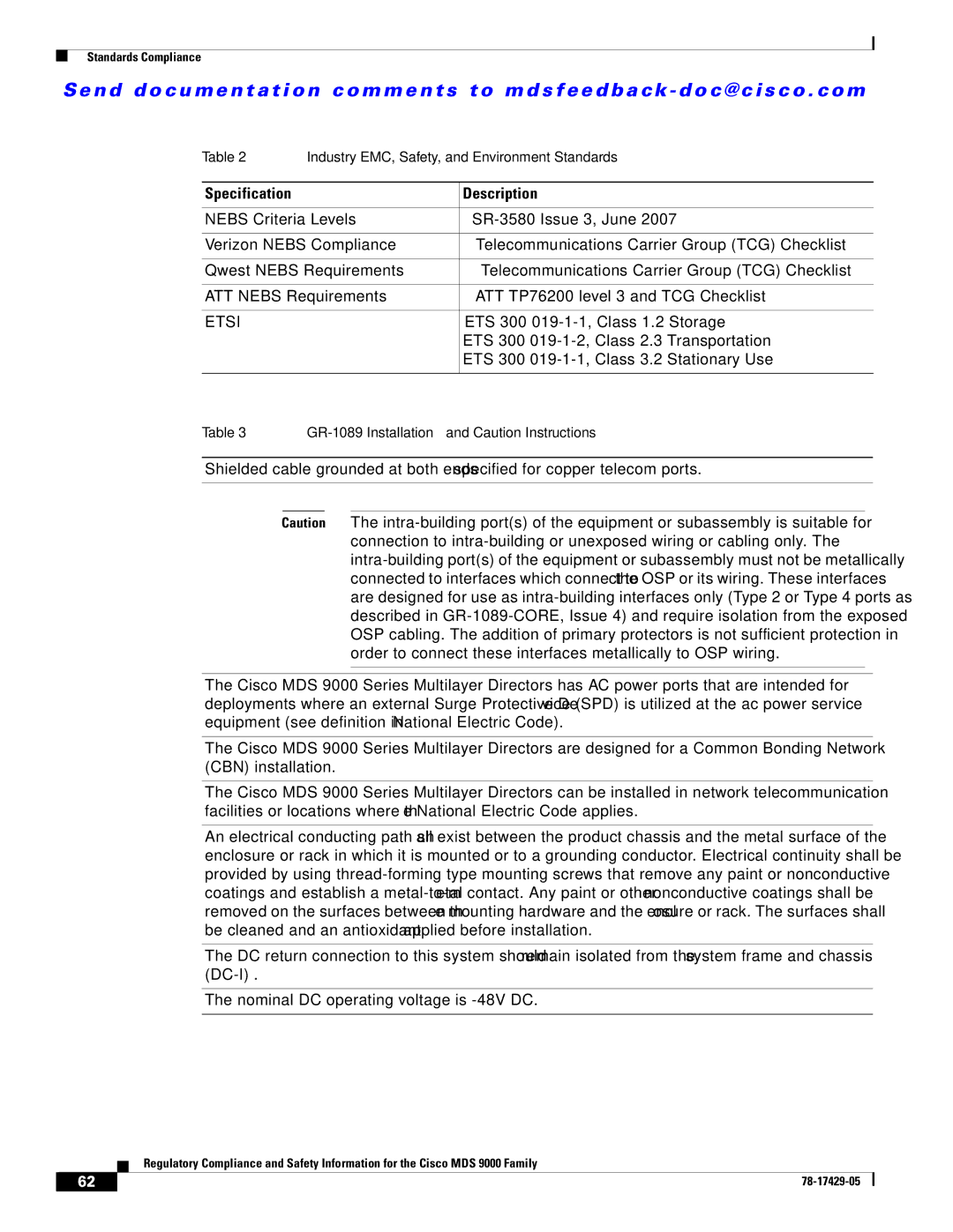
Table 2 | Industry EMC, Safety, and Environment Standards |
| |
|
|
|
|
Specification |
| Description |
|
|
| ||
NEBS Criteria Levels | |||
|
| ||
Verizon NEBS Compliance | Telecommunications Carrier Group (TCG) Checklist | ||
|
| ||
Qwest NEBS Requirements | Telecommunications Carrier Group (TCG) Checklist | ||
|
| ||
ATT NEBS Requirements | ATT TP76200 level 3 and TCG Checklist | ||
|
|
| |
ETSI |
| ETS 300 | |
|
| ETS 300 | Transportation |
|
| ETS 300 | Stationary Use |
|
|
|
|
Table 3 |
Shielded cable grounded at both ends specified for copper telecom ports.
Caution The
The Cisco MDS 9000 Series Multilayer Directors has AC power ports that are intended for deployments where an external Surge Protective Device (SPD) is utilized at the ac power service equipment (see definition in National Electric Code).
The Cisco MDS 9000 Series Multilayer Directors are designed for a Common Bonding Network (CBN) installation.
The Cisco MDS 9000 Series Multilayer Directors can be installed in network telecommunication facilities or locations where the National Electric Code applies.
An electrical conducting path shall exist between the product chassis and the metal surface of the enclosure or rack in which it is mounted or to a grounding conductor. Electrical continuity shall be provided by using
The DC return connection to this system should remain isolated from the system frame and chassis
The nominal DC operating voltage is
Regulatory Compliance and Safety Information for the Cisco MDS 9000 Family
62 |
| |
|