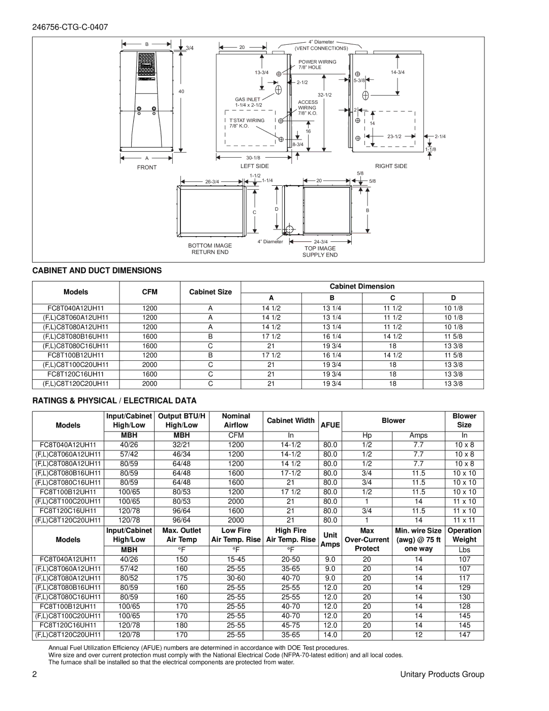
FC8T-UH, LC8T-UH specifications
The Coleman LC8T-UH and FC8T-UH are versatile heating solutions designed to provide effective warmth in diverse settings, whether at home, in a workshop, or during outdoor activities. Here, we’ll explore the main features, technologies, and characteristics that make these units stand out in the crowded heating market.Both models boast a powerful heating capacity, ensuring reliable warmth even in extreme cold conditions. Their robust design allows for efficient heating while maintaining energy efficiency, making them an economical choice for consumers mindful of their energy usage.
One of the standout characteristics of the Coleman LC8T-UH is its user-friendly control panel, which enables easy adjustments to temperature settings. The intuitive interface ensures users can quickly find their comfort level without complicated programming or excessive trial and error.
The FC8T-UH model, on the other hand, incorporates advanced heating technologies designed to maximize performance and heat distribution. This model features a patented heating element configuration that provides even warmth across a large area, ensuring no cold spots are left unattended.
Safety is paramount in the design of the LC8T-UH and FC8T-UH. Both models are equipped with multiple safety features, including overheat protection, which automatically shuts off the unit if it starts to overheat. This is particularly important for users who might leave the heater running for extended periods, offering peace of mind.
Portability is another key feature of these models. Equipped with built-in handles and lightweight construction, both the LC8T-UH and FC8T-UH can be easily moved from room to room or taken along on outdoor adventures.
Durability is a hallmark of Coleman products, and these heating units are no exception. Built with high-quality materials that withstand wear and tear, both models are designed for long-term use.
In conclusion, the Coleman LC8T-UH and FC8T-UH represent a blend of efficiency, safety, and portability, making them ideal choices for anyone in need of reliable heating solutions. Whether you’re heating your garage, workshop, or outdoor space, these models are designed to meet varied demands, ensuring comfort and warmth when it’s most needed. By combining user-friendly features with advanced technologies, Coleman continues to uphold its reputation as a leader in the heating industry.

