Connect Tech
Connectors/Pinouts
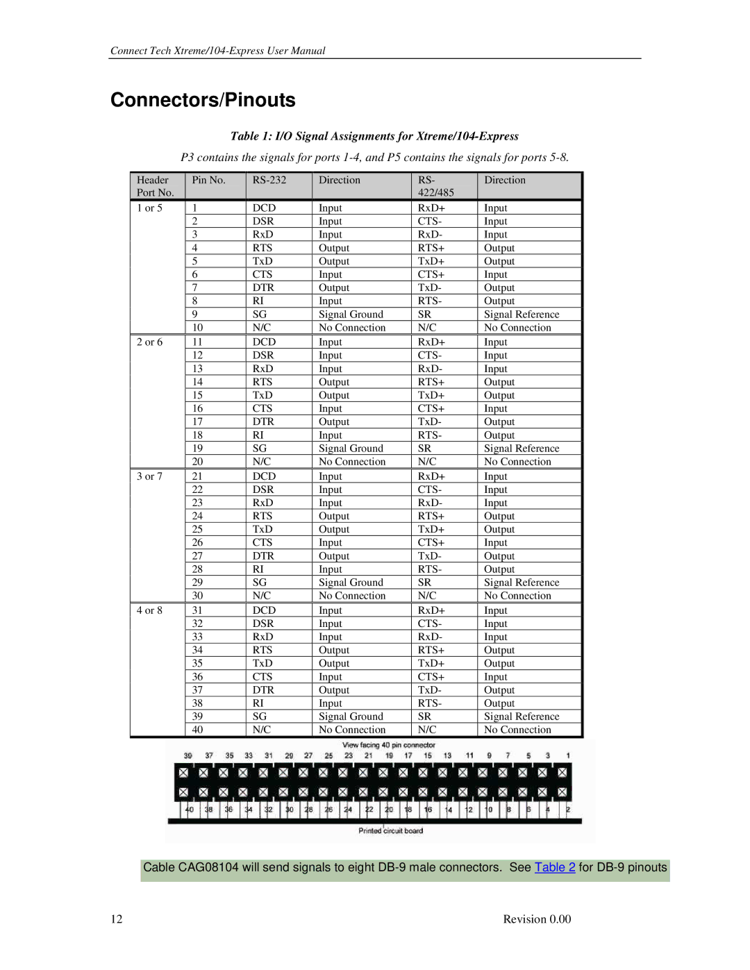
Table 1: I/O Signal Assignments for Xtreme/104-Express
P3 contains the signals for ports
Header | Pin No. | Direction | RS- | Direction | |
Port No. |
|
|
| 422/485 |
|
1 or 5 | 1 | DCD | Input | RxD+ | Input |
| 2 | DSR | Input | CTS- | Input |
| 3 | RxD | Input | RxD- | Input |
| 4 | RTS | Output | RTS+ | Output |
| 5 | TxD | Output | TxD+ | Output |
| 6 | CTS | Input | CTS+ | Input |
| 7 | DTR | Output | TxD- | Output |
| 8 | RI | Input | RTS- | Output |
| 9 | SG | Signal Ground | SR | Signal Reference |
| 10 | N/C | No Connection | N/C | No Connection |
2 or 6 | 11 | DCD | Input | RxD+ | Input |
| 12 | DSR | Input | CTS- | Input |
| 13 | RxD | Input | RxD- | Input |
| 14 | RTS | Output | RTS+ | Output |
| 15 | TxD | Output | TxD+ | Output |
| 16 | CTS | Input | CTS+ | Input |
| 17 | DTR | Output | TxD- | Output |
| 18 | RI | Input | RTS- | Output |
| 19 | SG | Signal Ground | SR | Signal Reference |
| 20 | N/C | No Connection | N/C | No Connection |
3 or 7 | 21 | DCD | Input | RxD+ | Input |
| 22 | DSR | Input | CTS- | Input |
| 23 | RxD | Input | RxD- | Input |
| 24 | RTS | Output | RTS+ | Output |
| 25 | TxD | Output | TxD+ | Output |
| 26 | CTS | Input | CTS+ | Input |
| 27 | DTR | Output | TxD- | Output |
| 28 | RI | Input | RTS- | Output |
| 29 | SG | Signal Ground | SR | Signal Reference |
| 30 | N/C | No Connection | N/C | No Connection |
4 or 8 | 31 | DCD | Input | RxD+ | Input |
| 32 | DSR | Input | CTS- | Input |
| 33 | RxD | Input | RxD- | Input |
| 34 | RTS | Output | RTS+ | Output |
| 35 | TxD | Output | TxD+ | Output |
| 36 | CTS | Input | CTS+ | Input |
| 37 | DTR | Output | TxD- | Output |
| 38 | RI | Input | RTS- | Output |
| 39 | SG | Signal Ground | SR | Signal Reference |
| 40 | N/C | No Connection | N/C | No Connection |
Cable CAG08104 will send signals to eight
12 | Revision 0.00 |