Cooper Bussmann
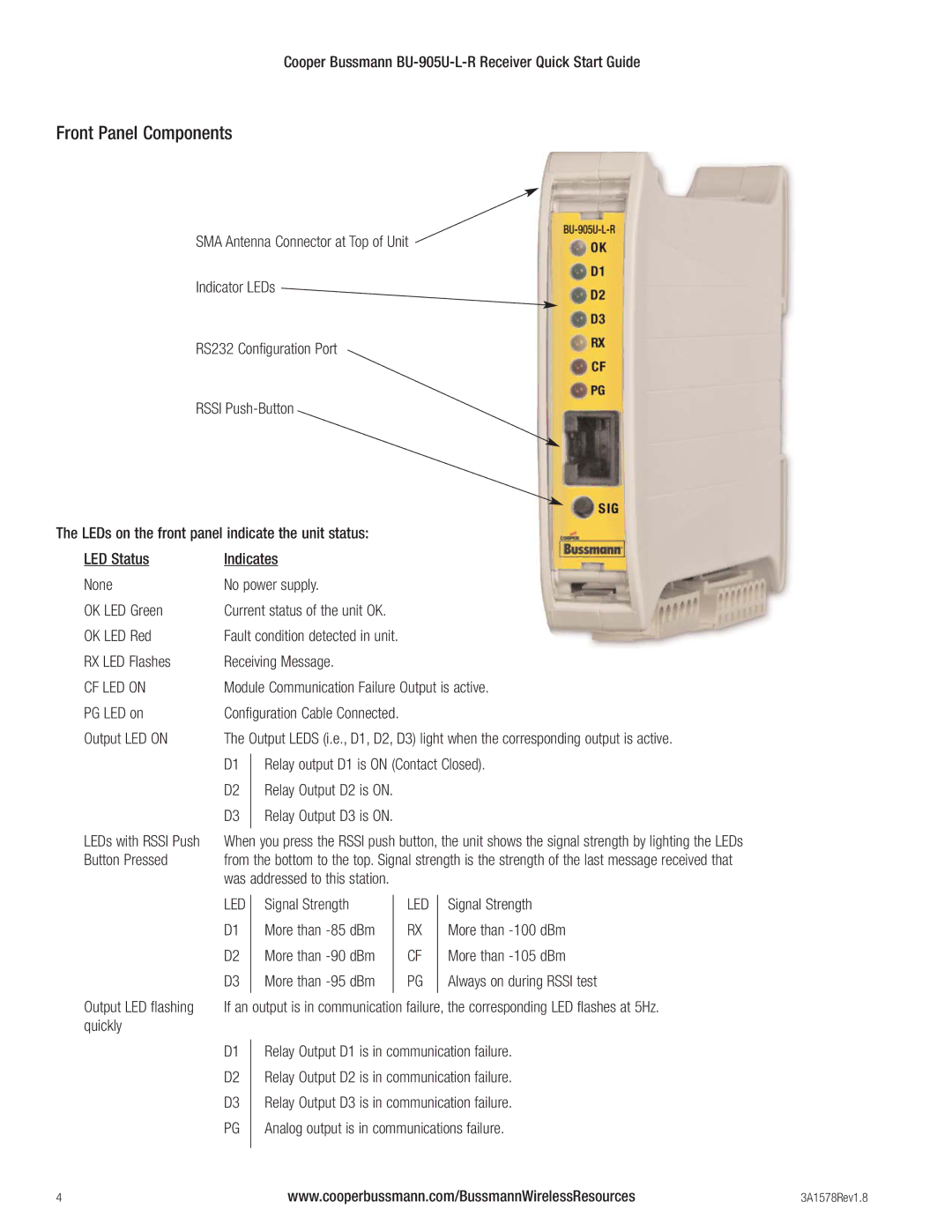
Front Panel Components
SMA Antenna Connector at Top of Unit
Indicator LEDs
RS232 Configuration Port
RSSI
The LEDs on the front panel indicate the unit status: |
|
|
| ||||
LED Status | Indicates |
|
|
| |||
None | No power supply. |
|
|
| |||
OK LED Green | Current status of the unit OK. |
|
|
| |||
OK LED Red | Fault condition detected in unit. |
|
|
| |||
RX LED Flashes | Receiving Message. |
|
|
| |||
CF LED ON | Module Communication Failure Output is active. | ||||||
PG LED on | Configuration Cable Connected. |
|
|
| |||
Output LED ON | The Output LEDS (i.e., D1, D2, D3) light when the corresponding output is active. | ||||||
| D1 |
| Relay output D1 is ON (Contact Closed). | ||||
|
| ||||||
| D2 |
| Relay Output D2 is ON. |
|
|
| |
| D3 |
| Relay Output D3 is ON. |
|
|
| |
LEDs with RSSI Push | When you press the RSSI push button, the unit shows the signal strength by lighting the LEDs | ||||||
Button Pressed | from the bottom to the top. Signal strength is the strength of the last message received that | ||||||
| was addressed to this station. |
|
|
| |||
| LED |
| Signal Strength |
| LED |
| Signal Strength |
|
|
|
| ||||
| D1 |
| More than |
| RX |
| More than |
| D2 |
| More than |
| CF |
| More than |
| D3 |
| More than |
| PG |
| Always on during RSSI test |
Output LED flashing | If an output is in communication failure, the corresponding LED flashes at 5Hz. | ||||||
quickly |
|
|
|
|
|
|
|
D1
D2
D3 PG
Relay Output D1 is in communication failure. Relay Output D2 is in communication failure. Relay Output D3 is in communication failure. Analog output is in communications failure.
4 | www.cooperbussmann.com/BussmannWirelessResources | 3A1578Rev1.8 |