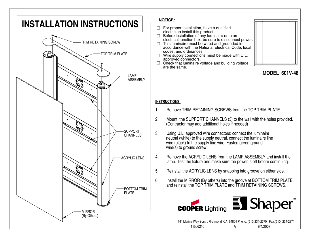
601V-48 specifications
The Cooper Lighting 601V-48 is an innovative lighting solution ideal for various commercial and industrial applications. Designed for versatility and efficiency, this high-quality light fixture stands out due to its array of features and technologies.One of the primary characteristics of the Cooper Lighting 601V-48 is its robust construction. Made from durable materials, the fixture is built to withstand harsh environmental conditions while maintaining its performance over time. This resilience makes it an excellent choice for settings such as warehouses, manufacturing plants, and outdoor areas.
The fixture boasts an impressive lumen output, providing bright, uniform lighting that enhances visibility in any workspace. With a color temperature option of around 5000K, it mimics daylight, which can significantly improve productivity and reduce eye strain for workers operating under its illumination.
Energy efficiency is another standout feature of the Cooper Lighting 601V-48. The fixture incorporates advanced LED technology, which not only provides high-quality light but also consumes significantly less energy compared to traditional lighting solutions. This energy-saving capability translates into lower electricity bills and a reduced carbon footprint, making it an environmentally friendly option.
Another advantage of this lighting fixture is its easy installation and maintenance. The design allows for quick mounting options, and the long lifespan of the LED technology means less frequent replacements are needed, simplifying ongoing maintenance efforts.
The Cooper Lighting 601V-48 is also compatible with advanced controls and smart technology. This compatibility allows for integration into building management systems, enabling users to maximize energy savings through the use of occupancy and daylight sensors. Such features help ensure that the lighting is only active when needed, further contributing to operational efficiency.
Overall, the Cooper Lighting 601V-48 combines durability, efficiency, and modern technology, making it a leading choice for a wide range of lighting applications. Whether for enhancing safety in busy industrial areas or for improving work conditions in commercial environments, this fixture offers a reliable and effective lighting solution that meets the demands of various settings.

