COOPER LIGHTING - METALUX®
RECESSED
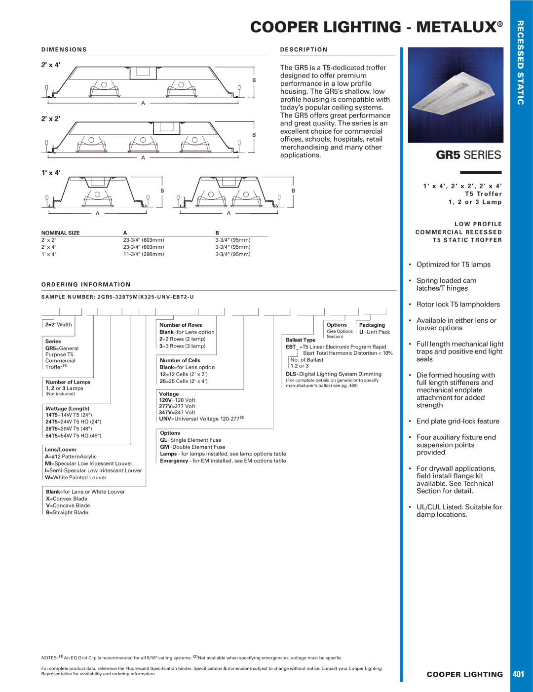
D I M E N S I O N S
2' x 4'
2' x 2'
1' x 4'
NOMINAL SIZE | A | B |
2' x 2' | ||
2' x 4' | ||
1' x 4' |
D E S C R I P T I O N
The GR5 is a
GR5 SERIES
1 ' x 4 ' , 2 ' x 2 ' , 2 ' x 4 ' T 5 Tr o f f e r 1 , 2 o r 3 L a m p
L O W P R O F I L E C O M M E R C I A L R E C E S S E D T 5 S TAT I C T R O F F E R
STATIC
O R D E R I N G I N F O R M AT I O N
S A M P L E N U M B E R : 2 G R 5 - 3 2 8 T 5 M I X 3 2 5 - U N V - E B T 2 - U
• Optimized for T5 lamps | |
• | Spring loaded cam |
| latches/T hinges |
• Rotor lock T5 lampholders | |
• | Available in either lens or |
2=2' Width
Series
GR5=General
Purpose T5
Commercial
Troffer (1)
Number of Lamps 1, 2 or 3 Lamps
(Not included)
Wattage (Length)
14T5=14W T5 (24")
24T5=24W T5 HO (24")
28T5=28W T5 (48")
54T5=54W T5 HO (48")
Lens/Louver
A=#12 PatternAcrylic
MI=Specular Low Iridescent Louver
W=White Painted Louver
Blank=for Lens or White Louver X=Convex Blade V=Concave Blade B=Straight Blade
|
|
|
|
|
|
|
|
|
|
|
|
|
|
|
|
|
|
|
|
|
|
|
|
|
|
|
|
|
|
|
|
|
|
|
|
|
|
|
|
|
|
|
|
|
|
|
|
Number of Rows |
|
|
|
|
|
|
|
|
|
|
|
|
| Options |
| Packaging | |||||||
Blank=for Lens option |
|
|
|
|
|
|
|
|
|
|
|
|
| (See Options |
| U=Unit Pack | |||||||
2=2 Rows (2 lamp) |
|
|
|
|
|
|
|
| Ballast Type |
| Section) |
|
|
|
|
| |||||||
|
|
|
|
|
|
|
|
|
|
|
|
|
|
|
| ||||||||
3=3 Rows (3 lamp) |
|
|
|
|
|
| EBT =T5 Linear Electronic Program Rapid | ||||||||||||||||
|
|
|
|
|
|
|
|
|
|
|
|
| Start Total Harmonic Distortion < 10% | ||||||||||
Number of Cells |
|
|
|
|
|
|
| No. | of Ballast |
|
|
|
| ||||||||||
Blank=for Lens option |
|
|
|
|
|
| 1,2 or 3 |
|
|
|
| ||||||||||||
|
|
|
|
|
|
|
|
|
|
| |||||||||||||
12=12 Cells (2' x 2') |
|
|
|
|
| DLS=Digital Lighting System Dimming | |||||||||||||||||
25=25 Cells (2' x 4') |
|
|
|
|
| (For complete details on generic or to specify | |||||||||||||||||
|
|
|
|
|
|
|
|
| manufacturer’s ballast see pg. 469) |
|
|
|
| ||||||||||
|
|
|
|
|
|
|
|
|
|
|
|
|
|
|
|
|
|
|
|
|
|
|
|
Voltage |
|
|
|
|
|
|
|
|
|
|
|
|
|
|
|
|
| ||||||
120V=120 Volt |
|
|
|
|
|
|
|
|
|
|
|
|
|
|
|
|
| ||||||
277V=277 Volt |
|
|
|
|
|
|
|
|
|
|
|
|
|
|
|
|
| ||||||
347V=347 Volt |
|
|
|
|
|
|
|
|
|
|
|
|
|
|
|
|
| ||||||
UNV=Universal Voltage |
|
|
|
|
|
|
|
|
|
|
|
|
|
|
|
|
| ||||||
|
|
|
|
|
|
|
|
|
|
|
|
|
|
|
|
|
|
|
|
|
|
|
|
Options |
|
|
|
|
|
|
|
|
|
|
|
|
|
|
| ||||||||
GL=Single Element Fuse |
|
|
|
|
|
|
|
|
|
|
|
|
|
|
| ||||||||
GM=Double Element Fuse |
|
|
|
|
|
|
|
|
|
|
|
|
|
|
| ||||||||
Lamps - for lamps installed, see lamp options table |
|
|
|
|
|
|
|
|
|
|
|
|
|
|
| ||||||||
Emergency - for EM installed, see EM options table |
|
|
|
|
|
|
|
|
|
|
|
|
|
|
| ||||||||
louver options |
• Full length mechanical light |
traps and positive end light |
seals |
• Die formed housing with |
full length stiffeners and |
mechanical endplate |
attachment for added |
strength |
• End plate |
• Four auxiliary fixture end |
suspension points |
provided |
• For drywall applications, |
field install flange kit |
available. See Technical |
Section for detail. |
• UL/CUL Listed. Suitable for |
damp locations. |
NOTES: (1)An EQ Grid Clip is recommended for all 9/16" ceiling systems. (2)Not available when specifying emergencies, voltage must be specific. |
|
For complete product data, reference the Fluorescent Specification binder. Specifications & dimensions subject to change without notice. Consult your Cooper Lighting | COOPER LIGHTING |
Representative for availability and ordering information. |
401