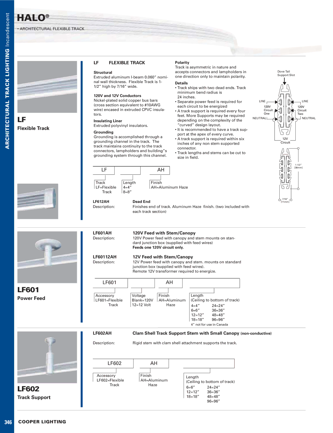
LF, LF602, LF601 specifications
Cooper Lighting has long been a leader in the world of lighting solutions, providing innovative products designed to enhance both functionality and aesthetics in residential, commercial, and industrial environments. Among their notable offerings are the LF, LF602, and LF601 models, which reflect the company’s commitment to cutting-edge technology and sustainable practices.The Cooper Lighting LF series is recognized for its sleek design and high-efficiency lighting solutions. One of the standout features of the LF series is its advanced LED technology, which delivers exceptional illumination while significantly reducing energy consumption. Compared to traditional incandescent or fluorescent lights, LEDs offer a longer lifespan and lower heat output, making them an environmentally friendly choice.
Specifically, the LF602 model combines performance with versatility. It is engineered for easy installation and can be utilized in various applications, from commercial spaces to residential settings. Its adjustable beam angles and color temperature options allow users to customize lighting based on their specific needs, creating an inviting atmosphere. The LF602 also employs a durable housing design that offers superior thermal management, ensuring longevity and consistent performance.
On the other hand, the LF601 model focuses on providing a streamlined solution for lighting in areas that require both reliability and aesthetic appeal. With a minimalist profile, the LF601 can seamlessly blend into any interior environment while still delivering impressive brightness levels. This model also incorporates smart lighting controls, including dimming and sensor capabilities, enhancing energy efficiency further.
Additionally, both the LF602 and LF601 series are built with sustainability in mind. They utilize materials that are recyclable and have been designed to minimize the production of waste during manufacturing. Cooper Lighting’s commitment to eco-friendly practices ensures that these products not only perform well but also contribute positively to environmental conservation.
In summary, Cooper Lighting’s LF, LF602, and LF601 models exemplify the future of lighting technology, combining energy efficiency, versatility, and sustainability. Whether you are illuminating a home, office, or industrial space, these products offer reliable performance and sophisticated design, making them an excellent choice for any lighting project. With continued innovations and a focus on customer satisfaction, Cooper Lighting sets a high standard in the lighting industry.