Manuals
/
Cooper Lighting
/
Household Appliance
/
Indoor Furnishings
Cooper Lighting
LF605, LF603 POWER HUB CONNECTOR 4 LF604 & LF606 Fig, inch, 703218, Halo
Models:
LF604
LF605
LF603
LF606
1
2
3
3
Download
3 pages
6.12 Kb
1
2
3
Safety
Page 2
Image 2
Page 1
Page 3
Page 2
Image 2
Page 1
Page 3
Contents
SAVE THESE INSTRUCTIONS
HALO
LF603, LF604, LF605, LF606
GARDER CES DIRECTIVES
LF604
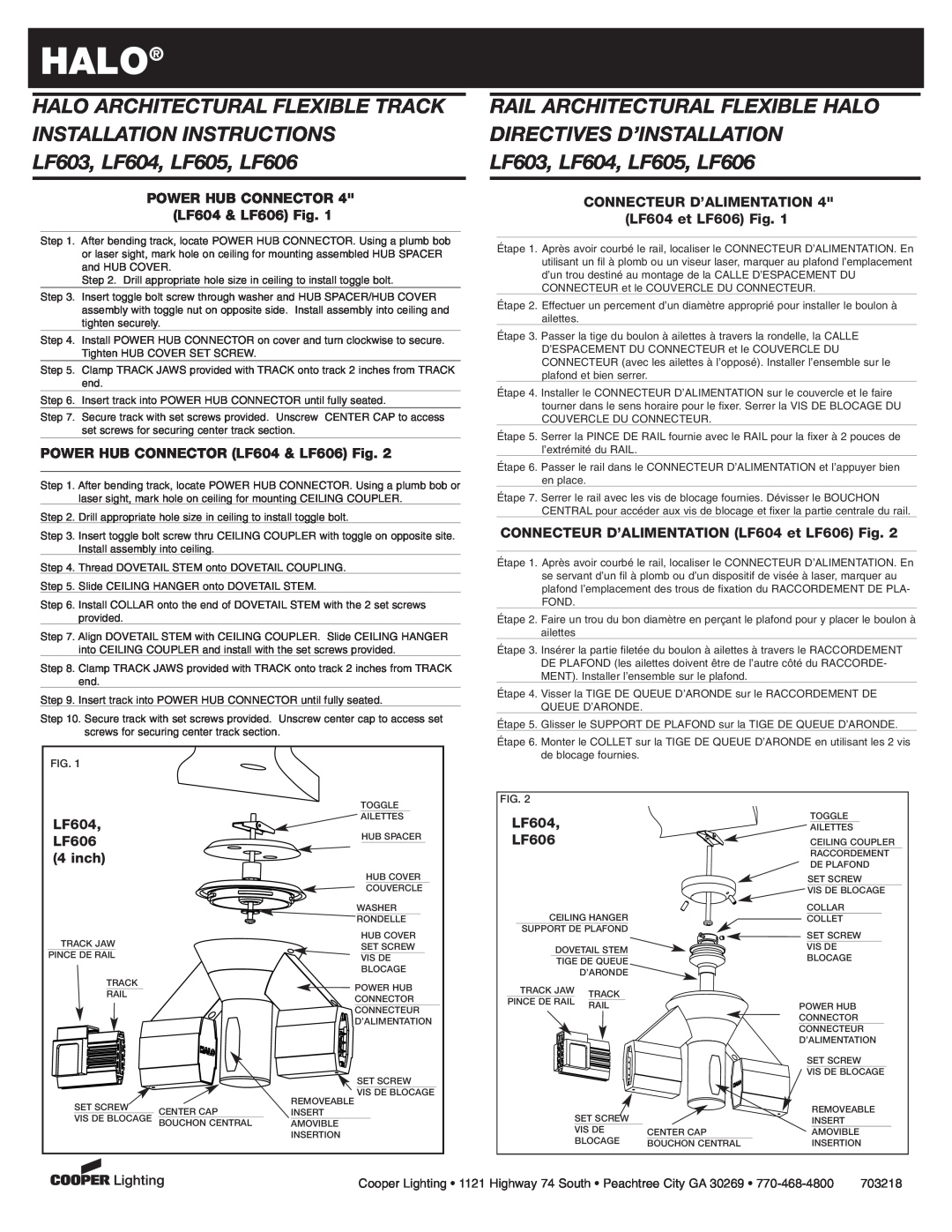
POWER HUB CONNECTOR 4 LF604 & LF606 Fig
POWER HUB CONNECTOR LF604 & LF606 Fig
LF606
LF603
POWER FEED HUB LF603 & LF605 Fig
STEM CUTTING INSTRUCTIONS
LF605
Top
Page
Image
Contents