COOPER LIGHTING
OPERATION
Step 1 Lamps or one lamp
Step 3 Release switch and lamp should extinguish.
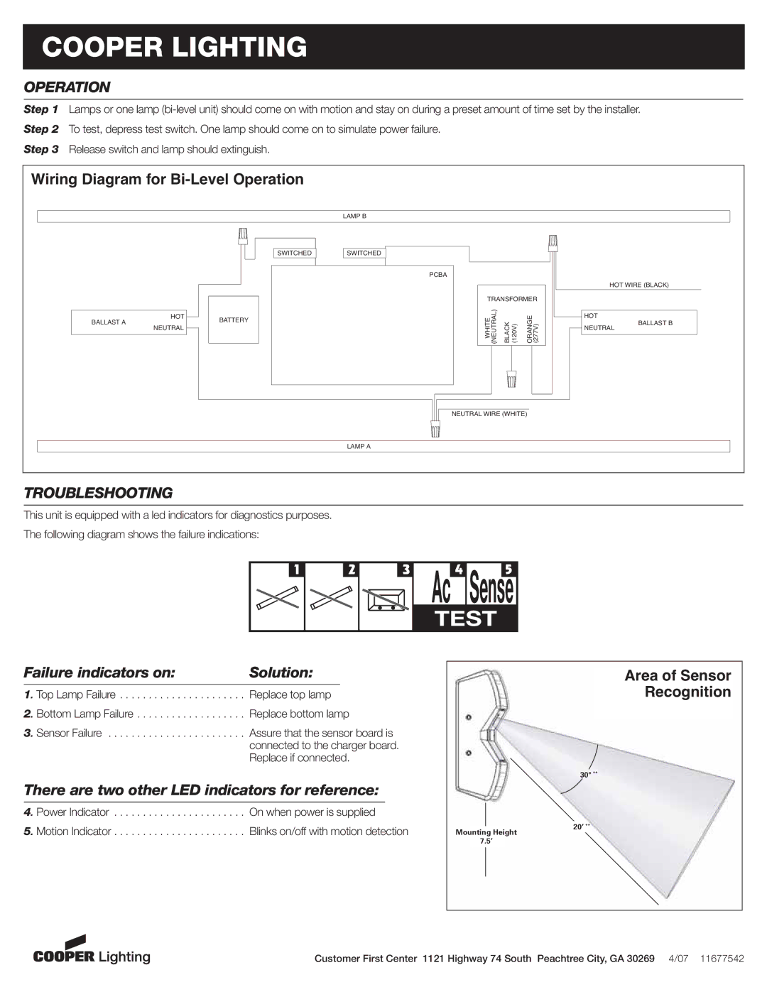
Wiring Diagram for
LAMP B
SWITCHED SWITCHED
BALLAST A | HOT | BATTERY |
| ||
NEUTRAL |
| |
|
|
LAMP A
TROUBLESHOOTING
This unit is equipped with a led indicators for diagnostics purposes. The following diagram shows the failure indications:
PCBA
TRANSFORMER
WHITE (NEUTRAL) | BLACK (120V) | ORANGE (277V) |
NEUTRAL WIRE (WHITE)
HOT WIRE (BLACK)
HOT
BALLAST B
NEUTRAL
1
2
3
Ac4 Sense5
TEST
Failure indicators on: | Solution: |
1. Top Lamp Failure . . . . . . . . . . . . . . . . . . . . . . Replace top lamp
2. Bottom Lamp Failure . . . . . . . . . . . . . . . . . . . Replace bottom lamp
3. Sensor Failure . . . . . . . . . . . . . . . . . . . . . . . . Assure that the sensor board is connected to the charger board. Replace if connected.
There are two other LED indicators for reference:
4. Power Indicator | On when power is supplied |
5. Motion Indicator | Blinks on/off with motion detection |
Area of Sensor
Recognition
30° **
20’ **
Mounting Height
7.5’
Customer First Center 1121 Highway 74 South Peachtree City, GA 30269 4/07 11677542