®BV-60/6212 All-Tube Professional Series Guitar Amplifiers
100V - 125V T2.5A
230V - 250V T1.5A
|
|
| CAUTION |
|
|
| RISK OF ELECTRIC SHOCK |
|
|
| DO NOT OPEN |
|
|
| RISQUE DE CHOC ELECTRIQUE. |
|
|
| AVIS:NE PAS OUVRIR |
|
|
| WARNING: TO REDUCE THE RISK OF FIRE OR |
|
|
| ELECTRICAL SHOCK, SO NOT EXPOSE THIS EQUIP- |
|
|
| MENT TO RAIN OR MOISTURE. |
|
|
| CAUTION: TO REDUCE THE |
|
|
| RISK OF FIRE, REPLACE |
AC LINE IN | FUSE WITH SAME TYPE AND | ||
RATING . | |||
|
|
| ATTENTION: UTILISER UN |
|
|
| FUSIBLE DE RECHARGE DE |
|
|
| MEME TYPE . |
| M A D E | I N T H E |
|
|
|
|
|
|
|
|
|
|
|
|
| U . S . A . |
|
|
|
|
|
|
|
|
|
|
|
| |
B Y S L M E L E C T R O N I C S – 1 4 0 0 F E R G U S O N A V E . – S T . L O U I S , M O . 6 3 1 3 3 |
|
| ||||||||||||
| U . S . P A T E N T # 5 , 0 1 2 , 1 9 9 |
|
|
|
|
|
|
|
|
|
|
|
| |
|
|
|
|
|
|
|
|
|
|
|
|
|
|
|
|
|
|
|
|
|
|
|
| MODEL |
|
| |||
CH. SEL | REVERB | SEND | RETURN |
|
| |||||||||
|
| |||||||||||||
|
| |||||||||||||
| FOOT |
|
|
|
|
|
| SERIAL # |
| BAL. | ||||
| EFFECTS |
| ||||||||||||
| SWITCH | LOOP |
|
|
|
|
|
|
|
| OUT | |||
|
|
|
|
|
|
|
|
|
| 360 WATTS MAX. |
| |||
TW0 16 OHM | TWO 8 OHM |
ENCLOSURES | ENCLOSURES |
ONE 8 OHM | ONE 4 OHM |
ENCLOSURE | ENCLOSURE |
| SPEAKER CONNECTIONS |
| 60 WATTS RMS |
|
|
|
|
|
|
|
|
|
|
|
|
|
|
|
|
|
|
|
|
|
18 | 19 | 20 | 21 | 22 | 23 | 24 | 25 | |||||||||||||
The Rear Panel:
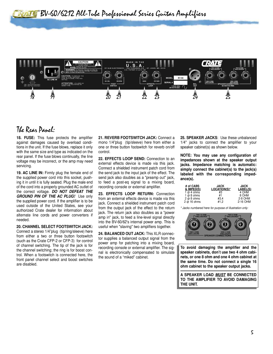
18.FUSE: This fuse protects the amplifier against damages caused by overload condi- tions in the unit. If the fuse blows, replace it only with the same size and type as indicated on the rear panel. If the fuse blows continually, the line voltage may be incorrect, or the amp may need servicing.
19.AC LINE IN: Firmly plug the female end of the supplied power cord into this socket, push- ing it in until it is fully seated. Plug the male end of the cord into a properly grounded AC outlet of the correct voltage. DO NOT DEFEAT THE GROUND PIN OF THE AC PLUG! Use only the supplied power cord. If the amplifier is to be used outside of the United States, see your authorized Crate dealer for information about alternate line cords and power converters if needed.
20.CHANNEL SELECT FOOTSWITCH JACK: Connect a stereo 1/4”plug (tip/ring/sleeve) here from either a two or three button footswitch (such as the Crate
21.REVERB FOOTSWITCH JACK: Connect a mono 1/4”plug (tip/sleeve) here from either a one or three button footswitch for reverb on/off control.
22.EFFECTS LOOP SEND: Connection to an external effects device is made via this jack. Connect a shielded instrument patch cord from the send jack to the input jack of the effect. The send jack also doubles as a "preamp out" jack, to feed a
23.EFFECTS LOOP RETURN: Connection from an external effects device is made via this jack. Connect a shielded instrument patch cord from the output jack of the effect to the return jack. The return jack also doubles as a "power amp in" jack, to feed a
24.BALANCED OUT JACK: This XLR connec- tor supplies a balanced output signal from the power amp for patching into a mixing board, recording console or external amplifier. The sig- nal is electronically compensated to simulate the sound of a “miked” cabinet.
25.SPEAKER JACKS: Use these unbalanced 1/4" jacks to connect the amplifier to your speaker cabinet(s) as shown below.
NOTE: You may use any configuration of impedances shown at the speaker output jacks. Impedance matching is automatic: simply connect the cabinet(s) to the jack(s) labeled with the corresponding imped- ance(s).
# of CABS | JACK | JACK |
& IMPED(S) | LOCATION(S)* | LABEL(S) |
1 @ 4 ohms | #3 | 4 OHM |
1 @ 8 ohms | #1 | 8 OHM |
2 @ 8 ohms | #3,4 | |
2 @ 16 ohms | #1,2 |
* Jacks numbered here for purpose of illustration only:
TW0 16 OHM |
|
|
| TWO 8 OHM |
ENCLOSURES |
|
|
| ENCLOSURES |
1 | 2 | 3 | 4 |
ONE 8 OHM | ONE 4 OHM |
ENCLOSURE | ENCLOSURE |
| SPEAKER CONNECTIONS |
To avoid damaging the amplifier and the speaker cabinets, don’t use two 4 ohm cabi- nets, or one 8 ohm and one 4 ohm cabinet at the same time. Do not connect a single 16 ohm cabinet to the speaker output jacks.
A SPEAKER LOAD MUST BE CONNECTED TO THE AMPLIFIER TO AVOID DAMAGING THE UNIT.
5
