Installation
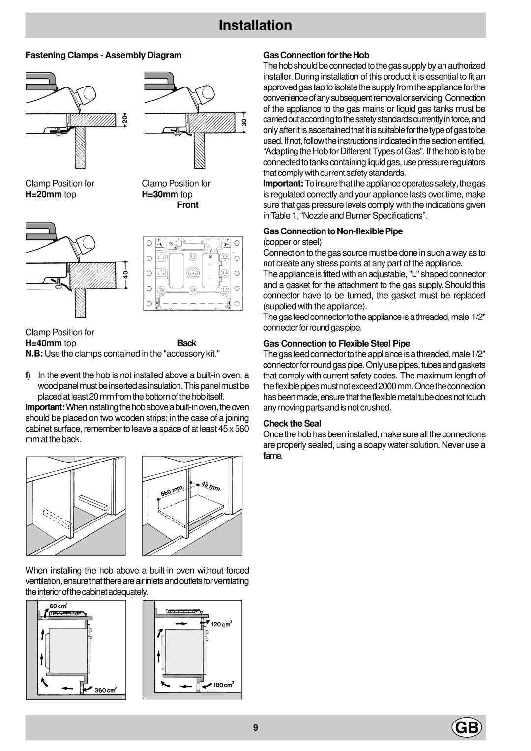
Fastening Clamps - Assembly Diagram
Clamp Position for | Clamp Position for | |
H=20mm top | H=30mm top | |
|
| Front |
|
|
|
|
|
|
Clamp Position for
H=40mm topBack
N.B: Use the clamps contained in the "accessory kit."
f)In the event the hob is not installed above a
Important:
. | 45 | mm. |
mm |
| |
560 |
|
|
When installing the hob above a
Gas Connection for the Hob
The hob should be connected to the gas supply by an authorized installer. During installation of this product it is essential to fit an approved gas tap to isolate the supply from the appliance for the convenienceofanysubsequentremovalorservicing.Connection of the appliance to the gas mains or liquid gas tanks must be carriedoutaccordingtothesafetystandardscurrentlyinforce,and only after it is ascertained that it is suitable for the type of gas to be used. If not, follow the instructions indicated in the section entitled, “Adapting the Hob for Different Types of Gas”. If the hob is to be connected to tanks containing liquid gas, use pressure regulators that comply with current safety standards.
Important: To insure that the appliance operates safety, the gas is regulated correctly and your appliance lasts over time, make sure that gas pressure levels comply with the indications given in Table 1, “Nozzle and Burner Specifications”.
Gas Connection to Non-flexible Pipe (copper or steel)
Connection to the gas source must be done in such a way as to not create any stress points at any part of the appliance.
The appliance is fitted with an adjustable, "L" shaped connector and a gasket for the attachment to the gas supply. Should this connector have to be turned, the gasket must be replaced (supplied with the appliance).
The gas feed connector to the appliance is a threaded, male 1/2" connectorforroundgaspipe.
Gas Connection to Flexible Steel Pipe
The gas feed connector to the appliance is a threaded, male 1/2" connector for round gas pipe. Only use pipes, tubes and gaskets that comply with current safety codes. The maximum length of theflexiblepipesmustnotexceed2000mm.Oncetheconnection hasbeenmade,ensurethattheflexiblemetaltubedoesnottouch any moving parts and is not crushed.
Check the Seal
Once the hob has been installed, make sure all the connections are properly sealed, using a soapy water solution. Never use a flame.
9