Carving | ||
Station | ||
| ||
Rev. 7 (4/08) | Page 2 of 2 | |
|
|
5925 Heisley Road • Mentor, OH
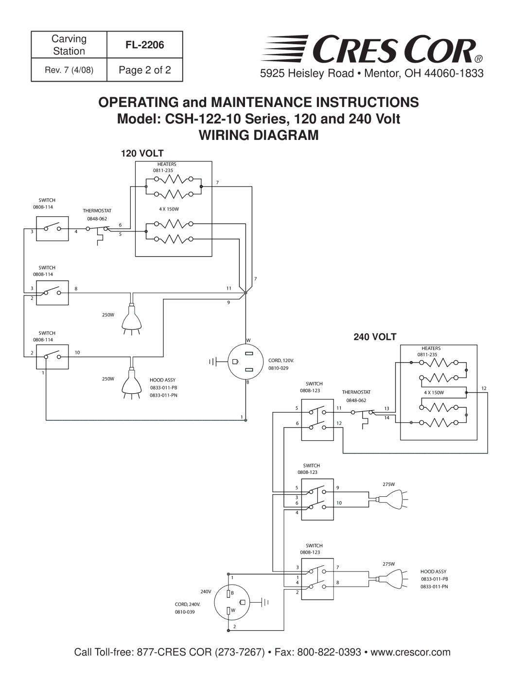
OPERATING and MAINTENANCE INSTRUCTIONS
Model:
WIRING DIAGRAM
|
| 120 VOLT |
|
|
|
| HEATERS |
|
|
|
|
|
| |
|
|
| 7 |
|
SWITCH |
|
|
|
|
THERMOSTAT | 4 X 150W |
|
| |
|
|
| ||
|
|
|
| |
|
|
|
| |
|
| 6 |
|
|
3 | 4 | 5 |
|
|
|
|
|
| |
SWITCH |
|
|
|
|
|
|
| 7 | |
|
|
|
| |
3 | 8 |
| 11 |
|
2 |
|
| 9 |
|
|
|
|
| |
| 250W |
|
|
|
SWITCH |
|
|
|
|
|
| W |
| |
2 | 10 |
|
|
|
|
|
|
| CORD, 120V. |
1 |
|
|
| |
|
|
|
| |
| 250W | HOOD ASSY | B | SWITCH |
|
|
| ||
|
|
| ||
|
|
| ||
|
|
| ||
|
|
|
| |
|
|
|
| 5 |
|
|
| 1 |
|
|
|
|
| 6 |
240 VOLT
HEATERS
THERMOSTAT | 12 |
4 X 150W | |
| |
11 | 13 |
| 14 |
12 |
|
SWITCH |
5 |
3 |
9
275W
6 |
4 |
SWITCH
10
3 |
7
275W
HOOD ASSY
| 1 | 1 |
| ||||||
|
|
| 4 |
| |||||
240V |
|
|
|
|
|
|
| ||
|
|
|
|
|
| ||||
| B |
|
|
| 2 |
| |||
|
|
|
|
| |||||
|
|
|
|
|
|
|
|
|
|
CORD, 240V. |
| W |
|
|
|
|
|
|
|
|
|
|
|
|
|
|
| ||
|
|
|
|
|
|
|
| ||
|
|
|
|
|
|
|
|
| |
![]()
![]()
![]()
![]()
2
Call