Crestron CNHBLOCK | Multi-Type Network Distribution Block |
Network Wiring
When calculating the wire gauge for a particular Cresnet run, the length of the run and the load factor of each network unit to be connected must be taken into consideration. If Cresnet units are to be daisy-chained on the run, the load factor of each unit to be daisy-chained must be added together to determine the load factor of the entire chain. If the unit is a home-run from a Crestron system power supply network port, the load factor of that unit is the load factor of the entire run. The length of the run in feet and the load factor of the run should be used in the following resistance equation to calculate the value on the right side of the equation.
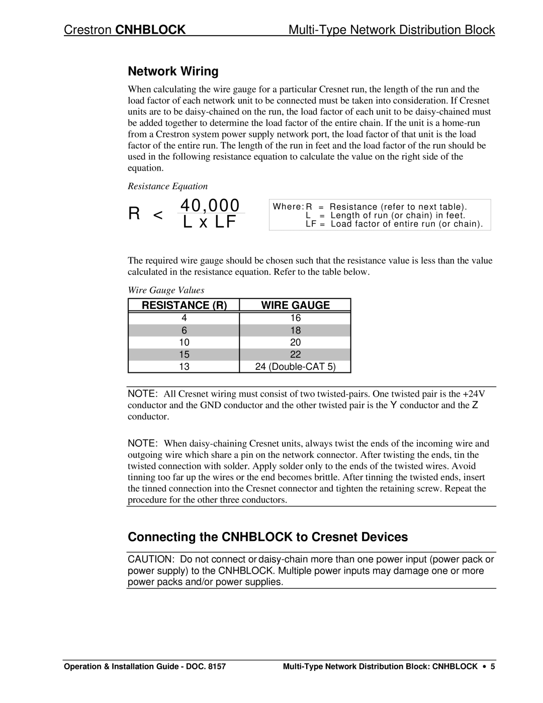
Resistance Equation
R < 40,000 L x LF
Where: R | = | Resistance (refer to next table). |
L | = | Length of run (or chain) in feet. |
LF = | Load factor of entire run (or chain). |
| | |
The required wire gauge should be chosen such that the resistance value is less than the value calculated in the resistance equation. Refer to the table below.
Wire Gauge Values
RESISTANCE (R) | WIRE GAUGE |
| |
4 | 16 |
6 | 18 |
10 | 20 |
| |
15 | 22 |
13 | 24 (Double-CAT 5) |
NOTE: All Cresnet wiring must consist of two twisted-pairs. One twisted pair is the +24V conductor and the GND conductor and the other twisted pair is the Y conductor and the Z conductor.
NOTE: When daisy-chaining Cresnet units, always twist the ends of the incoming wire and outgoing wire which share a pin on the network connector. After twisting the ends, tin the twisted connection with solder. Apply solder only to the ends of the twisted wires. Avoid tinning too far up the wires or the end becomes brittle. After tinning the twisted ends, insert the tinned connection into the Cresnet connector and tighten the retaining screw. Repeat the procedure for the other three conductors.
Connecting the CNHBLOCK to Cresnet Devices
CAUTION: Do not connect or daisy-chain more than one power input (power pack or power supply) to the CNHBLOCK. Multiple power inputs may damage one or more power packs and/or power supplies.
Operation & Installation Guide - DOC. 8157 | Multi-Type Network Distribution Block: CNHBLOCK ∙ 5 |