Micro-Tech Series Power Amplifiers

3 Setup

3.6 Wire Your System

3.6.1 Stereo Mode

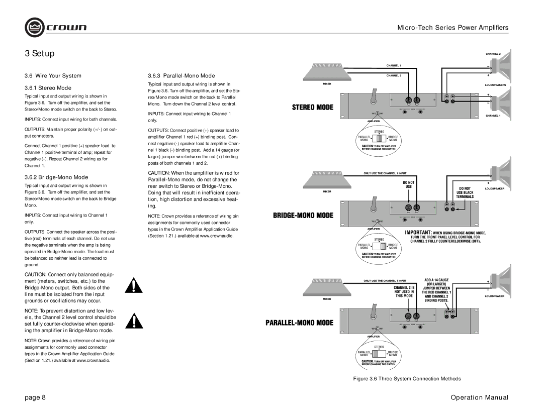
Typical input and output wiring is shown in Figure 3.6. Turn off the amplifier, and set the Stereo/Mono mode switch on the back to Stereo.

INPUTS: Connect input wiring for both channels.

OUTPUTS: Maintain proper polarity (+/-) on out- put connectors.

Connect Channel 1 positive (+) speaker load to Channel 1 positive terminal of amp; repeat for negative (-). Repeat Channel 2 wiring as for Channel 1.

3.6.2 Bridge-Mono Mode

Typical input and output wiring is shown in Figure 3.6. Turn off the amplifier, and set the Stereo/Mono mode switch on the back to Bridge Mono.

INPUTS: Connect input wiring to Channel 1 only.

OUTPUTS: Connect the speaker across the posi- tive (red) terminals of each channel. Do not use the negative terminals when the amp is being operated in Bridge-Mono mode. The load must be balanced so neither lead is connected to ground.

CAUTION: Connect only balanced equip- ment (meters, switches, etc.) to the Bridge-Mono output. Both sides of the line must be isolated from the input grounds or oscillations may occur.

NOTE: To prevent distortion and low lev- els, the Channel 2 level control should be set fully counter-clockwise when operat- ing the amplifier in Bridge-Mono mode.

NOTE: Crown provides a reference of wiring pin assignments for commonly used connector types in the Crown Amplifier Application Guide (Section 1.21.) available at www.crownaudio.

3.6.3 Parallel-Mono Mode

Typical input and output wiring is shown in Figure 3.6. Turn off the amplifier, and set the Ste- reo/Mono mode switch on the back to Parallel Mono. Turn down the Channel 2 level control.

INPUTS: Connect input wiring to Channel 1 only.

OUTPUTS: Connect positive (+) speaker load to amplifier Channel 1 red (+) binding post. Con- nect negative (-) speaker load to amplifier Chan- nel 1 black (-) binding post. Add a 14 gauge (or larger) jumper wire between the red (+) binding posts of both channels 1 and 2.

CAUTION: When the amplifier is wired for Parallel-Mono mode, do not change the rear switch to Stereo or Bridge-Mono. Doing that will result in inefficient opera- tion, high distortion and excessive heat- ing.

NOTE: Crown provides a reference of wiring pin assignments for commonly used connector types in the Crown Amplifier Application Guide (Section 1.21.) available at www.crownaudio.

Figure 3.6 Three System Connection Methods

page 8

Operation Manual

Page 8
Image 8
Crown 2400, 1200, 2401, 601 Wire Your System Stereo Mode, Bridge-Mono Mode, Inputs Connect input wiring to Channel 1 only

600, 2400, 1201, 1200, 2401 specifications

Crown 601, 2401, 1200, 1201, and 2400 represent a range of advanced technology products tailored for various industrial and commercial applications. Each model encapsulates cutting-edge features that enhance functionality, efficiency, and user experience.

Crown 601 is an innovative model designed primarily for warehousing and material handling. It incorporates a compact design that allows for maneuverability in tight spaces. One of its standout features is the advanced ergonomic design that reduces operator fatigue, enhancing productivity. Equipped with high-efficiency electric motors, the Crown 601 offers low energy consumption while providing a powerful performance capable of lifting substantial loads.

The Crown 2401 model is renowned for its versatility in various settings. This model features a robust construction that withstands rigorous use, making it ideal for outdoor applications. It is powered by superior lithium-ion technology, ensuring better performance and reduced downtime due to its fast charging capabilities. The 2401 model also integrates smart technology, enabling real-time tracking and monitoring through IoT connectivity. This feature empowers businesses to optimize their operations by analyzing usage patterns and performance metrics.

The Crown 1200 and 1201 models focus on maneuverability and ease of use, tailored for indoor operations. They come equipped with advanced steering systems that enable precise handling in congested areas. Additionally, the 1201 variant includes features like programmable performance parameters, which allow operators to customize the equipment’s speed and responsiveness based on specific operational needs. Both models prioritize safety, including built-in stability controls to minimize tipping hazards during operation.

Meanwhile, the Crown 2400 model stands out for its heavy-duty performance, supporting higher load capacities while maintaining operational efficiency. It incorporates advanced hydraulic systems that enhance lifting speeds and precision. The 2400's design houses features such as regenerative braking, providing additional energy savings and longer battery life.

In conclusion, the Crown 601, 2401, 1200, 1201, and 2400 represent a top tier selection in material handling solutions, each equipped with unique technologies and features designed to cater to diverse industrial needs. With their focus on ergonomics, safety, and efficiency, these models exemplify Crown's commitment to innovation and quality, ensuring optimal performance in any application.