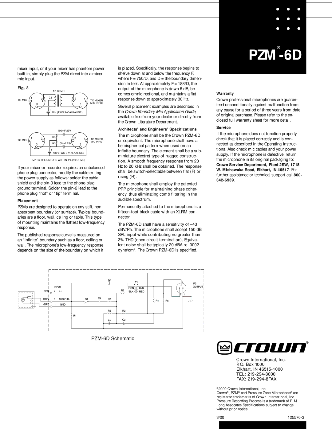
mixer input, or if your mixer has phantom power built in, simply plug the PZM direct into a mixer mic input.
Fig. 3
|
| 1:1 XFMR |
|
| |
1 | 2 | CT | 2 | 1 | TO MIXER |
TO MIC |
|
|
|
| |
| 3 |
|
| 3 | MIC INPUT |
|
|
|
| ||
|
| + |
|
|
|
|
| 18V (TWO |
| ||
|
|
| 100mF 25V |
|
|
|
|
| + |
|
|
1 | 2 | 1K | 2 | 1 | TO MIXER |
| |||||
TO MIC |
|
|
|
| MIC INPUT |
| 3 | 1K | 100mF 25V | 3 | |
|
| ||||
|
| + |
| ||
+
18V (TWO
MATCH RESISTORS WITHIN 1% (10 OHMS)
If your mixer or recorder requires an unbalanced phone plug connector, modify the cable exiting the power supply as follows: solder the cable shield and the
Placement
PZMs are designed to operate on any stiff, non- absorbent boundary (or surface). Typical bound- aries are a floor, wall, ceiling or table. This type of mounting maintains the flattest
The published response curve is measured on an “infinite” boundary such as a floor, ceiling or wall. The microphone’s
is placed. Specifically, the response begins to shelve down at and below the frequency F, where F = 750/D, and D = the boundary dimen- sion in feet. At approximately F = 188/D, the output of the microphone is down 6 dB, be- comes omnidirectional, and maintains a flat response down to approximately 30 Hz.
Several placement examples are described in the Crown Boundary Mic Application Guide, available free from your dealer or directly from the Crown Literature Department.
Architects’ and Engineers’ Specifications
The microphone shall be the Crown
The microphone shall employ the patented PRP principle for maintaining phase coher- ency, thus eliminating comb filtering in the audible spectrum.
Permanently attached to the microphone is a
The
PZM®-6D
Warranty
Crown professional microphones are guaran- teed unconditionally against malfunction from any cause for a period of three years from date of original purchase. Please refer to the en- closed full warranty sheet for more detail.
Service
If the microphone does not function properly, check that it is placed correctly and is con- nected as described in the Operating Instruc- tions. Also check mic cables and your power supply. If the microphone is defective, return the microphone in its original packaging to:
Crown Service Department, Plant 2SW, 1718 W. Mishawaka Road, Elkhart, IN 46517. For further assistance or technical support call 800-
PZM-6D Schematic
Crown International, Inc.
P. O. Box 1000
Elkhart, IN 46515-1000
TEL: 219-294-8000
FAX: 219-294-8FAX
©2000 Crown International, Inc.
Crown®, PZM® and Pressure Zone Microphone® are registered trademarks of Crown International, Inc. Pressure Recording Process is a trademark of E. M. Long Assocates.Specifications subject to change without prior notice.
3/00 | ||
|
|
|
