I-TECH SERIES
Specifications
Performance
Frequency Response
(at 1 watt, 20 Hz - 20 kHz): ±0.25dB.
Signal to Noise Ratio
below rated power, A-weighted: >105 dB
Total Harmonic Distortion (THD)
at full rated power: < 0.35%.
Intermodulation Distortion (IMD) 60 Hz and 7 kHz at 4:1, from full rated output to –35 dB: < 0.35%.
Damping Factor (20 Hz to 100 Hz): > 5000.
Crosstalk (below rated power, 20 Hz to 1 kHz): > 80 dB.
Common Mode Rejection (CMR) (20 Hz to 1 kHz): > 50 dB.
DC Output Offset: < ± 3 mV. Input Impedance (nominal):
20 kilohms balanced, 10 kilohms unbalanced.
Maximum Input Level: +15 dBu or +22 dBu, depending on input sensitivity.
Latency (analog, digital inputs): 1.13 mS analog, 2.36 mS digital (44.1 kHz).
A/D, D/A Converters: 24-bit 96 kHz Cirrus Logic.
Digital Input: AES/EBU, 16-24 bit, 32-48 kHz. Onboard sample rate converter.
Network: Onboard TCP/IQ, compatible with standard 100 Mb Ethernet hardware.
DSP: 24-bit conversion with 32-bit, floating-point DSP processing. Has 64 assignable filters with 9 different filter types. Includes all-pass filters, over
2 seconds of delay available per channel, and dual uncorrelated-noise and sine-wave generators.
Load Supervision: Monitors the average impedance on the output of the amplifier. If the impedance falls outside the specified high/low limits, this function alerts the user via the front panel display, and via the IQwic™ software when amp is on an IQ Network.
Error Reporting: Reports clip errors, thermal errors, fault conditions and load monitoring errors for each channel via the front panel display and via IQwic software when amp is on an IQ Network.
Attenuators: Speed sensitive, continuously variable rotary encoder, 0.5 dB steps, range 0 to –90 dB.
Load Impedance (Note: Safe with all types of loads):
Stereo: 1/2/4/8/16 ohms. Bridge Mono: 2/4/8 ohms.
Input Sensitivity (referenced to 8 ohm rated output): Adjustable in 0.1V steps from 1.4V to 7.75V.
AC Line Connector: Five cordsets supplied with amplifier (USA, UK, European, Australia, India).
Voltage Gain (referenced to 8 ohm rated output): I-T4000: 37.1 dB to 22.2 dB
I-T6000: 37.9 dB to 23.0 dB
I-T8000: 39.3 dB to 24.5 dB
Required AC Mains: Universal AC input, 100-240VAC, 50/60 Hz (±15%). Maximum AC mains voltage 277VAC.
Front Panel Controls and Indicators
Bridge Mode Indicator: Yellow LED illuminates when the LCD control screen is set to Bridge-Mono mode.
Ready Indicator: Green LED, one per channel, illuminates when the channel is initialized and ready to produce audio output. Indicator is off when the amplifier is in standby mode via the IQ system.
Signal Indicators: Three green LEDs per channel indicate the amplifier’s input and output signal levels.
Signal: input signal is above –40 dBu.
–20 dB: amplifier output is 20 dB below clipping.
–10 dB: amplifier output is 10 dB below clipping.
Clip Indicator: Red LED, one per channel, illuminates when the channel’s output signal reaches the onset of audible clipping. The Clip Indicator also will illuminate during Thermal Level Control (TLC) limiting or when the input compressor/limiter is protecting the amplifier from input overload.
Thermal Indicator: Red LED, one per channel, illuminates when the channel has shut down, or is very near shutting down, due to thermal stress or overload.
Fault Indicator: Red LED, one per channel, flashes when the amplifier output channel has stopped operating.
Data Indicator: Yellow LED indicates IQ Network data activity. Data indicator flashes only when the amplifier is polled for data, or is polled to see whether it is online.
Power Indicator: Blue LED indicates amplifier has been turned on and AC power is available. The LED will flash when the AC line voltage is 15% above or below the nominal rated value.
AC Mains Present Indicator: Green indicator built into power switch indicates AC power present at the power cord and the amplifier circuit braker is in the “on” position.
LCD Control Screen and Controls: These let the user adjust the amplifier’s attenuation and muting, configure the amp, set up error monitoring (such as temperature and load supervision), and recall DSP presets. The presets allow the user to quickly reconfigure the amp for various applictions.
LCD Control Screen: Integrated LCD with white LED backlight, controls amplifier setup and operation.
Normal mode: Attenuation in 0.5 dB steps, Mute/Unmute, Front Panel Lockout.
Basic Menu: LCD Contrast, CH1 Sensitivity, CH2 Sensitivity, Speaker Preset, Dual/Bridge mode, Input Y.
Advanced Features Menu: Attenuator Limits, Attenuator Link, Clip Limiter, Peak Voltage Limiter, Average Power Limiter, Pink Noise Generator, AES/EBU Input Trim, Input Source, Maximum Analog Input, Amplifier Label Edit, CH1 Label Edit, CH2 Label Edit.
Menu/Exit Button: “Menu” enters the main menu. “Exit” gets out of the Menu.
Next Button: Selects the next item in the Menu.
Prev Button: Selects the previous item in the Menu.
Level Controls (Encoders): These two knobs affect the Channel-1 and Channel-2 output levels. They also select Menu items and adjust parameter values that are displayed on the LCD Control Screen.
Power Switch: Push-on/push-off switch with built-in green AC mains present indicator.
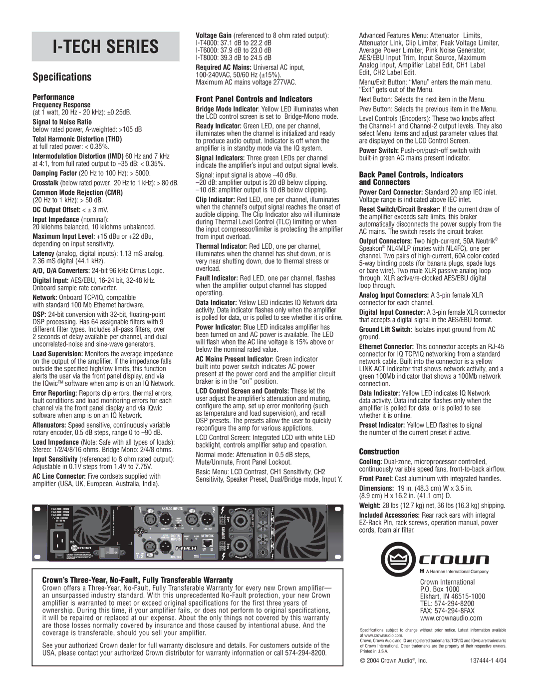
Back Panel Controls, Indicators and Connectors
Power Cord Connector: Standard 20 amp IEC inlet. Voltage range is indicated above IEC inlet.
Reset Switch/Circuit Breaker: If the current draw of the amplifier exceeds safe limits, this braker automatically disconnects the power supply from the AC mains. The switch resets the circuit braker.
Output Connectors: Two high-current, 50A Neutrik® Speakon® NL4MLP (mates with NL4FC), one per channel. Two pairs of high-current, 60A color-coded 5-way binding posts (for banana plugs, spade lugs or bare wire). Two male XLR passive analog loop through. XLR active/re-clocked AES/EBU digital loop through.
Analog Input Connectors: A 3-pin female XLR connector for each channel.
Digital Input Connector: A 3-pin female XLR connector that accepts a digital signal in the AES/EBU format.
Ground Lift Switch: Isolates input ground from AC ground.
Ethernet Connector: This connector accepts an RJ-45 connector for IQ TCP/IQ networking from a standard network cable. Built into the connector is a yellow LINK ACT indicator that shows network activity, and a green 100Mb indicator that shows a 100Mb network connection.
Data Indicator: Yellow LED indicates IQ Network data activity. Data indicator flashes only when the amplifier is polled for data, or is polled to see whether it is online.
Preset Indicator: Yellow LED flashes to signal the number of the current preset if active.
Construction
Cooling: Dual-zone, microprocessor controlled, continuously variable speed fans, front-to-back airflow.
Front Panel: Cast aluminum with integrated handles.
Dimensions: 19 in. (48.3 cm) W x 3.5 in.
(8.9 cm) H x 16.2 in. (41.1 cm) D.
Weight: 28 lbs (12.7 kg) net, 36 lbs (16.3 kg) shipping.
Included Accessories: Rear rack ears with integral EZ-Rack Pin, rack screws, operation manual, power cords, foam air filter.