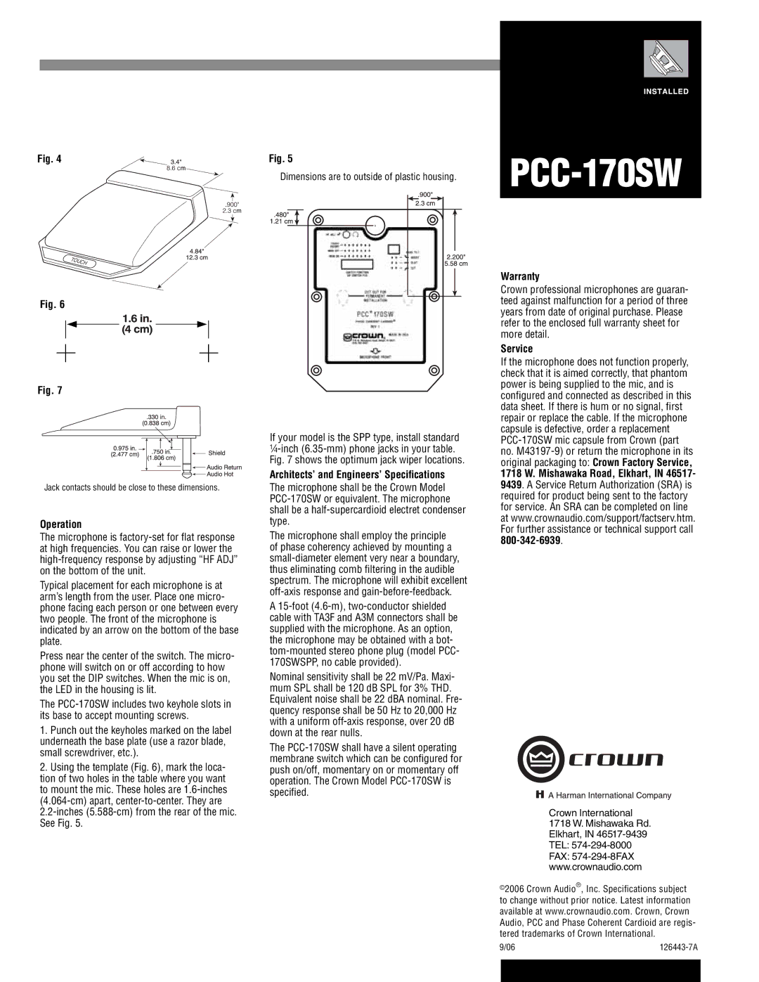
Fig. 4
Fig. 6
Fig. 7
Jack contacts should be close to these dimensions.
Operation
The microphone is
Typical placement for each microphone is at arm’s length from the user. Place one micro- phone facing each person or one between every two people. The front of the microphone is indicated by an arrow on the bottom of the base plate.
Press near the center of the switch. The micro- phone will switch on or off according to how you set the DIP switches. When the mic is on, the LED in the housing is lit.
The
1.Punch out the keyholes marked on the label underneath the base plate (use a razor blade, small screwdriver, etc.).
2.Using the template (Fig. 6), mark the loca- tion of two holes in the table where you want to mount the mic. These holes are
Fig. 5
Dimensions are to outside of plastic housing.
If your model is the SPP type, install standard
Architects’ and Engineers’ Specifications
The microphone shall be the Crown Model
The microphone shall employ the principle of phase coherency achieved by mounting a
A
Nominal sensitivity shall be 22 mV/Pa. Maxi- mum SPL shall be 120 dB SPL for 3% THD. Equivalent noise shall be 22 dBA nominal. Fre- quency response shall be 50 Hz to 20,000 Hz with a uniform
The
PCC-170SW
Warranty
Crown professional microphones are guaran- teed against malfunction for a period of three years from date of original purchase. Please refer to the enclosed full warranty sheet for more detail.
Service
If the microphone does not function properly, check that it is aimed correctly, that phantom power is being supplied to the mic, and is configured and connected as described in this data sheet. If there is hum or no signal, first repair or replace the cable. If the microphone capsule is defective, order a replacement
Crown International 1718 W. Mishawaka Rd. Elkhart, IN
©2006 Crown Audio®, Inc. Specifications subject to change without prior notice. Latest information available at www.crownaudio.com. Crown, Crown Audio, PCC and Phase Coherent Cardioid are regis- tered trademarks of Crown International.
9/06 | ||
|
|
|
|
|
|
