Power-Tech .1 Series Power Amplifiers
4Operation
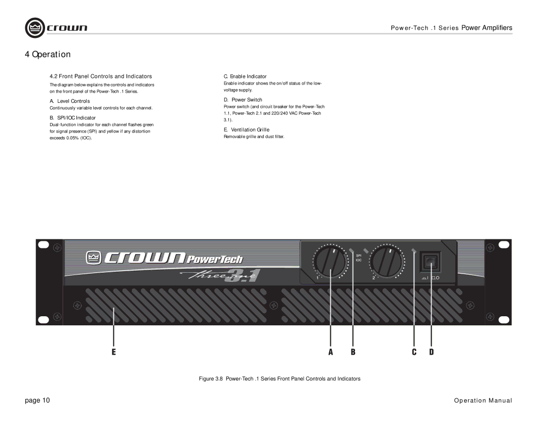
4.2Front Panel Controls and Indicators
The diagram below explains the controls and indicators on the front panel of the
A. Level Controls
Continuously variable level controls for each channel.
B. SPI/IOC Indicator
C. Enable Indicator
Enable indicator shows the on/off status of the low- voltage supply.
D. Power Switch
Power switch (and circuit breaker for the
E.Ventilation Grille Removable grille and dust filter.
Figure 3.8 Power-Tech .1 Series Front Panel Controls and Indicators
page 10 | Operation Manual |