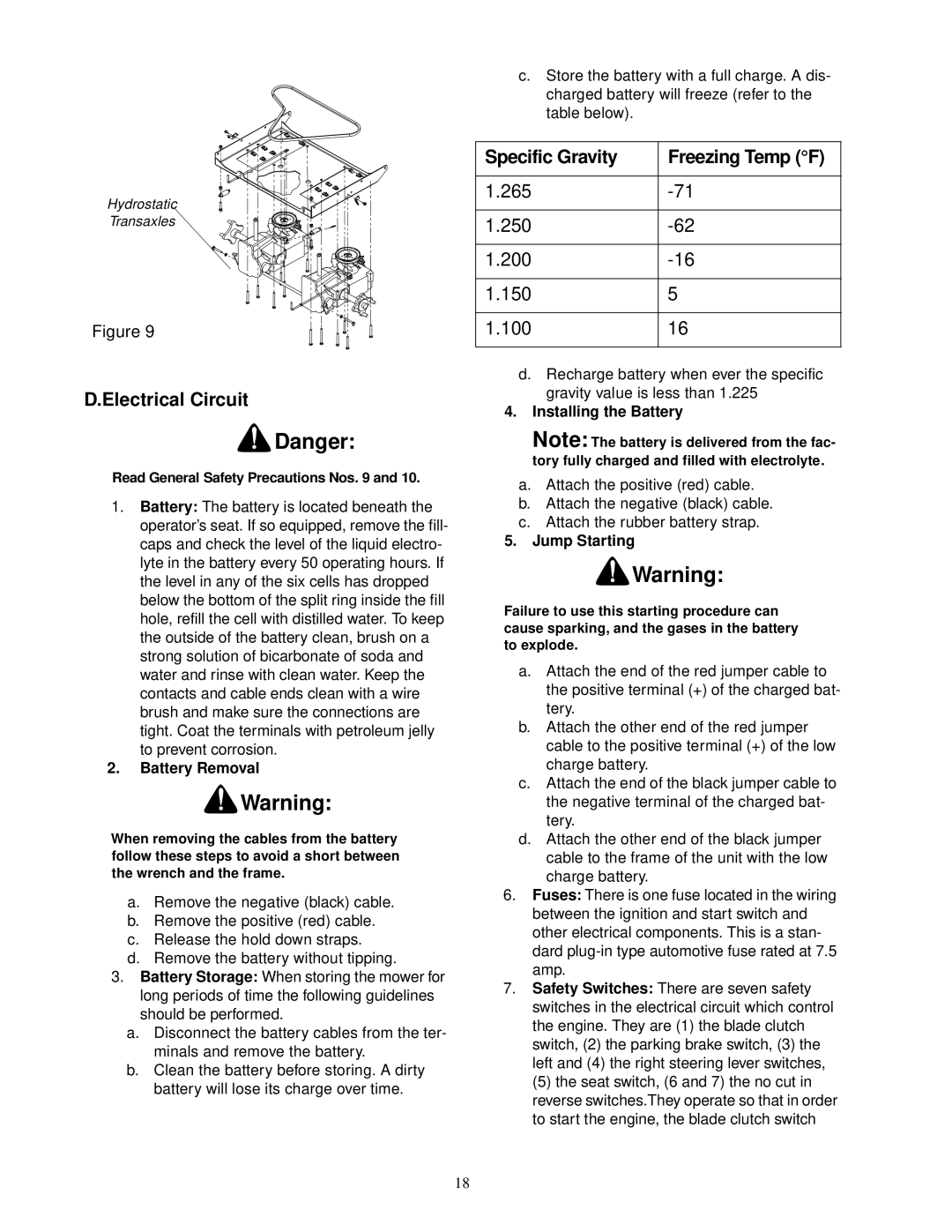
Hydrostatic
Transaxles
Figure 9
D.Electrical Circuit
![]() Danger:
Danger:
Read General Safety Precautions Nos. 9 and 10.
1.Battery: The battery is located beneath the operator’s seat. If so equipped, remove the fill- caps and check the level of the liquid electro- lyte in the battery every 50 operating hours. If the level in any of the six cells has dropped below the bottom of the split ring inside the fill hole, refill the cell with distilled water. To keep the outside of the battery clean, brush on a strong solution of bicarbonate of soda and water and rinse with clean water. Keep the contacts and cable ends clean with a wire brush and make sure the connections are tight. Coat the terminals with petroleum jelly to prevent corrosion.
2.Battery Removal
![]() Warning:
Warning:
When removing the cables from the battery follow these steps to avoid a short between the wrench and the frame.
a.Remove the negative (black) cable.
b.Remove the positive (red) cable.
c.Release the hold down straps.
d.Remove the battery without tipping.
3.Battery Storage: When storing the mower for long periods of time the following guidelines should be performed.
a.Disconnect the battery cables from the ter- minals and remove the battery.
b.Clean the battery before storing. A dirty battery will lose its charge over time.
c.Store the battery with a full charge. A dis- charged battery will freeze (refer to the table below).
Specific Gravity | Freezing Temp (°F) |
|
|
1.265 | |
|
|
1.250 | |
|
|
1.200 | |
|
|
1.150 | 5 |
|
|
1.100 | 16 |
|
|
d.Recharge battery when ever the specific gravity value is less than 1.225
4.Installing the Battery
Note: The battery is delivered from the fac- tory fully charged and filled with electrolyte.
a.Attach the positive (red) cable.
b.Attach the negative (black) cable.
c.Attach the rubber battery strap.
5.Jump Starting
![]() Warning:
Warning:
Failure to use this starting procedure can cause sparking, and the gases in the battery to explode.
a.Attach the end of the red jumper cable to the positive terminal (+) of the charged bat- tery.
b.Attach the other end of the red jumper cable to the positive terminal (+) of the low charge battery.
c.Attach the end of the black jumper cable to the negative terminal of the charged bat- tery.
d.Attach the other end of the black jumper cable to the frame of the unit with the low charge battery.
6.Fuses: There is one fuse located in the wiring between the ignition and start switch and other electrical components. This is a stan- dard
7.Safety Switches: There are seven safety switches in the electrical circuit which control the engine. They are (1) the blade clutch switch, (2) the parking brake switch, (3) the left and (4) the right steering lever switches,
(5) the seat switch, (6 and 7) the no cut in reverse switches.They operate so that in order to start the engine, the blade clutch switch
18