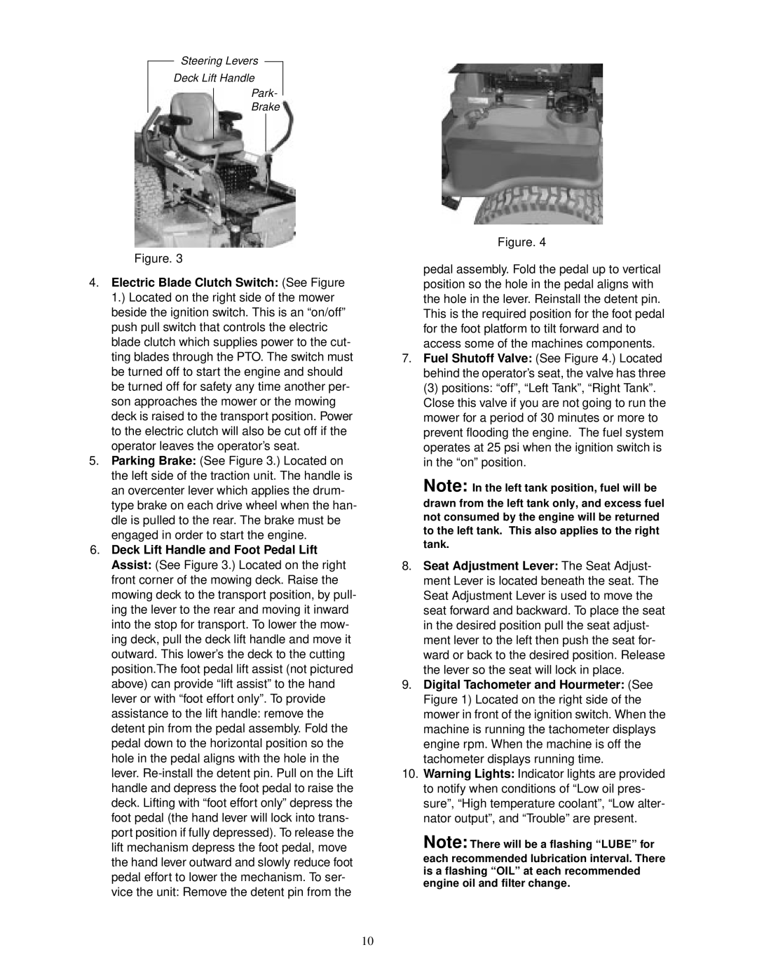
Steering Levers
Deck Lift Handle
Park-
Brake
Figure. 3
4.Electric Blade Clutch Switch: (See Figure 1.) Located on the right side of the mower beside the ignition switch. This is an “on/off” push pull switch that controls the electric blade clutch which supplies power to the cut- ting blades through the PTO. The switch must be turned off to start the engine and should be turned off for safety any time another per- son approaches the mower or the mowing deck is raised to the transport position. Power to the electric clutch will also be cut off if the operator leaves the operator’s seat.
5.Parking Brake: (See Figure 3.) Located on the left side of the traction unit. The handle is an overcenter lever which applies the drum- type brake on each drive wheel when the han- dle is pulled to the rear. The brake must be engaged in order to start the engine.
6.Deck Lift Handle and Foot Pedal Lift Assist: (See Figure 3.) Located on the right front corner of the mowing deck. Raise the mowing deck to the transport position, by pull- ing the lever to the rear and moving it inward into the stop for transport. To lower the mow- ing deck, pull the deck lift handle and move it outward. This lower’s the deck to the cutting position.The foot pedal lift assist (not pictured above) can provide “lift assist” to the hand lever or with “foot effort only”. To provide assistance to the lift handle: remove the detent pin from the pedal assembly. Fold the pedal down to the horizontal position so the hole in the pedal aligns with the hole in the lever.
Figure. 4
pedal assembly. Fold the pedal up to vertical position so the hole in the pedal aligns with the hole in the lever. Reinstall the detent pin. This is the required position for the foot pedal for the foot platform to tilt forward and to access some of the machines components.
7.Fuel Shutoff Valve: (See Figure 4.) Located behind the operator’s seat, the valve has three
(3) positions: “off”, “Left Tank”, “Right Tank”. Close this valve if you are not going to run the mower for a period of 30 minutes or more to prevent flooding the engine. The fuel system operates at 25 psi when the ignition switch is in the “on” position.
Note: In the left tank position, fuel will be drawn from the left tank only, and excess fuel not consumed by the engine will be returned to the left tank. This also applies to the right tank.
8.Seat Adjustment Lever: The Seat Adjust- ment Lever is located beneath the seat. The Seat Adjustment Lever is used to move the seat forward and backward. To place the seat in the desired position pull the seat adjust- ment lever to the left then push the seat for- ward or back to the desired position. Release the lever so the seat will lock in place.
9.Digital Tachometer and Hourmeter: (See Figure 1) Located on the right side of the mower in front of the ignition switch. When the machine is running the tachometer displays engine rpm. When the machine is off the tachometer displays running time.
10.Warning Lights: Indicator lights are provided to notify when conditions of “Low oil pres- sure”, “High temperature coolant”, “Low alter- nator output”, and “Trouble” are present.
Note: There will be a flashing “LUBE” for each recommended lubrication interval. There is a flashing “OIL” at each recommended engine oil and filter change.
10