OPERATING ELEMENTS
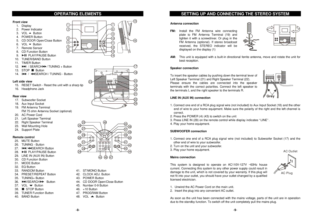
Front view |
|
| 15 | ||
1. | Display |
| 1 | 7 | |
2. | Power Indicator | 2 | 8 | ||
3. | VOL 5 Button |
| 9 | ||
4. | POWER Button | 3 | 10 | ||
5. | CD DOOR Open/Close Button | ||||
4 | 16 | ||||
6. | VOL 6 Button | 11 | |||
5 | 12 | ||||
7. | Remote Sensor | ||||
8. | CD Function Button | 6 | 13 | ||
9. | PLAY/PAUSE Button |
| 14 | ||
10. | TUNER/BAND Button |
|
| ||
11. | TIMER Button |
|
| ||
12. | / SEARCH / TUNING + Button | 17 | |||
13. | STOP | Button |
| 18 | |
14. | / | SEARCH / TUNING - Button | |||
| |||||
Left side view |
| 23 | 23 | ||
15. | RESET Switch - Reset the unit with a sharp tip | 19 | |||
16. | Headphone Jack |
| 20 | ||
Rear view |
|
| 21 | ||
|
|
| |||
17. | Subwoofer Socket | 22 |
18. | Aux Input Socket | 24 |
19. | FM Antenna Terminal |
|
| FM 75 ohm Antenna Socket (optional) |
|
20.AC Power Cord
21.Left Speaker Terminal
22. | Right Speaker Terminal | 25 | 48 | 35 | |
23. | Wall Mounting Hole | 26 |
| ||
| 36 | ||||
24. | Support Plate | 27 |
| 37 | |
28 |
| ||||
|
|
| 38 | ||
Remote control | 29 |
| 39 | ||
30 |
| 40 | |||
25. | MUTE Button | 31 |
| 41 | |
26. | TUNING - Button |
| |||
32 |
| 42 | |||
27. | / SEARCH Button | 33 |
| 43 | |
28. | PLAY/PAUSE Button | 34 |
| 44 | |
29. | LINE IN (AUX IN) Button | 45 | 46 | 47 | |
30. | CD Function Button | ||||
|
|
| |||
31.MODE Button
32.EQ Button
33. | RANDOM Button | 41. | ST/MONO Button | ||||
34. | PRESET/REPEAT Button | 42. | CLOCK ADJ. Button | ||||
35. | TUNING+ Button | 43. | POWER Button | ||||
36. |
|
| /SEARCH Button | 44. | CD DOOR Open/Close Button | ||
37. | VOL | Button | 45. | Number | |||
38. |
|
| STOP Button | 46. | +10 Button | ||
|
| ||||||
39. | TUNER Function Button | 47. | PROGRAM Button | ||||
40. | BAND Button | 48. | VOL | Button | |||
SETTING UP AND CONNECTING THE STEREO SYSTEM
Antenna connection
FM: Install the FM Antenna wire connecting plate to FM Antenna Terminal (19) and tighten it with a screwdriver. Or plug in the FM Antenna (optional). If stereo broadcast received, the STEREO indicator will be displayed on the display (1)
AM: This unit is equipped with a
Speaker connection
To insert the speaker cables by pushing down the terminal lever of Left Speaker Terminal (21) and Right Speaker Terminal (22). Please ensure the cables are connected into the speaker terminals with the correct polarities. Connect the left speaker to the terminals L and the right speaker to the terminals R.
LINE IN (AUX IN) connection | Grey |
|
1.Connect one end of a RCA plug signal wire (not included) to Aux Input Socket (18) and the other end of wire to your home equipment. Make sure the polarity of the right and the left channel is correct.
2.Press the POWER (4) (43) to switch on the unit
3.Press LINE IN (29) on the remote control while display indicates “LINE”.
4.Play your home equipment.
SUBWOOFER connection
1.Connect one end of a RCA plug signal wire (not included) to Subwoofer Socket (17) and the other end of wire to your subwoofer.
2.Turn on the unit and your subwoofer.
3. Play your home equipment.
Mains connection
This system is designed to operate on |
| |
current. Connecting this system to any other power supply could result in |
| |
damage to the unit, which is not covered by your warranty. If this plug will | AC Plug | |
not fit into your outlet, you should have your outlet changed by a qualified | ||
| ||
licensed electrician. |
|
1.Unwind the AC Power Cord on the main unit.
2.Insert the plug into any convenient AC outlet.
As soon as the unit has been connected with the mains voltage, parts of the unit are in operation due to the standby function. To switch off the unit completely pull the mains plug.