Manuals
/
CyberPower Systems
/
Computer Equipment
/
Power Supply
CyberPower Systems
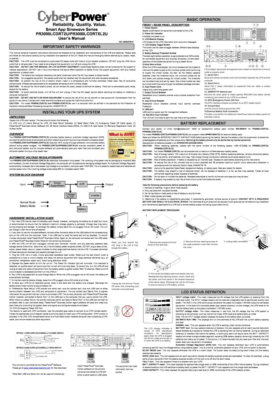
PR3000LCDRT2U
user manual
Basic Operation, Important Safety Warnings, Overview
Models:
PR3000LCDRT2U
1
1
2
2
Download
2 pages
60.67 Kb
1
2
Specs
Install
Page 1
Image 1
Page 1
Page 2
Page 1
Image 1
Page 1
Page 2
Contents
INSTALLING YOUR UPS SYSTEM
IMPORTANT SAFETY WARNINGS
BATTERY REPLACEMENT
BASIC OPERATION
CYBERPOWER GREENPOWER UPS TECHNOLOGY
LCD STATUS AND SETUP FUCTIONS
LIMITED WARRANTY AND CONNECTED EQUIPMENT GUARNTEE
TECHNICAL SPECIFICATIONS
Top
Page
Image
Contents