| Digital Modems |
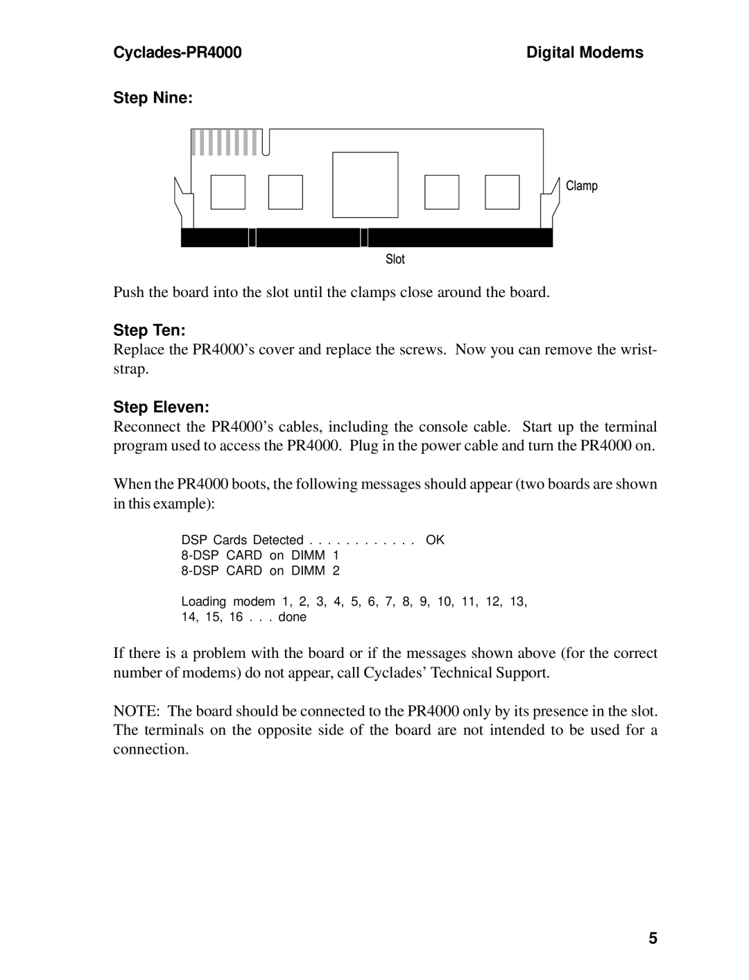
Step Nine:
Push the board into the slot until the clamps close around the board.
Step Ten:
Replace the PR4000’s cover and replace the screws. Now you can remove the wrist- strap.
Step Eleven:
Reconnect the PR4000’s cables, including the console cable. Start up the terminal program used to access the PR4000. Plug in the power cable and turn the PR4000 on.
When the PR4000 boots, the following messages should appear (two boards are shown in this example):
DSP Cards Detected . . . . . . . . . . . . OK
Loading modem 1, 2, 3, 4, 5, 6, 7, 8, 9, 10, 11, 12, 13, 14, 15, 16 . . . done
If there is a problem with the board or if the messages shown above (for the correct number of modems) do not appear, call Cyclades’ Technical Support.
NOTE: The board should be connected to the PR4000 only by its presence in the slot. The terminals on the opposite side of the board are not intended to be used for a connection.
5