Code 1: Subroutine for Reading Keypad
;Keypad.asm
;This routine reads a 4 column by 4 row
;keypad on port1. The status of key
;closures is returned in A.
;
;P1.4 P1.5 P1.6 P1.7
; | R0 | C0 | C1 | C2 | C3 |
; P1.0 | +- | ||||
; | R1 | ||||
; P1.1 | +- | ||||
; | R2 | ||||
; P1.2 | +- | ||||
; | R3 | ||||
; P1.3 | +- | ||||
; |
|
|
|
|
|
|
|
|
| ||
export | bReadKeypad |
|
| ||
export | _bReadKeypad |
|
| ||
include "m8c.inc" |
|
| |||
bReadKeypad: |
|
|
| ||
_bReadKeypad: |
|
|
| ||
mov | reg[PRT1DR], f0h | ;drive columns | |||
mov | X,SP |
|
|
| |
mov | A, reg[PRT1DR] | ;read rows | |||
mov | reg[PRT1DR], 0fh | ;drive rows | |||
push A |
|
| ;store row info on stack | ||
AN2034
Using the Output
The output of the function bReadKeypad is a single byte that shows the status of key closure of the keypad. It is translated and decoded as follows:
No bits are set if no key is pressed.
A single bit in the upper nibble and a single bit in the lower nibble are set for a
Any other condition is a
These rules can be decoded with discrete conditional code that breaks up the byte into two nibbles to determine row and column information. Use this information to determine which key, if any, was pressed. This results in a complex set of rules and is tedious.
Another scheme is to use a lookup table to decode this data. The advantage is that the table stores the formatted data. Different programmers could be working on the same project and each use their own table to decode the keypad when they are required to read it.
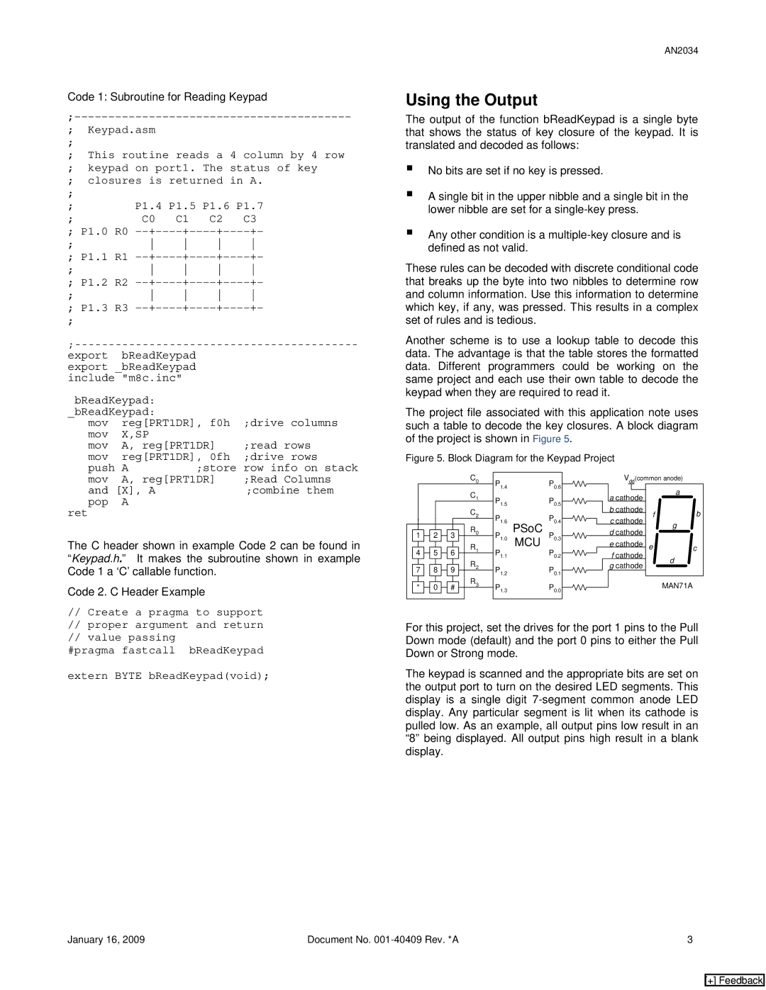
The project file associated with this application note uses such a table to decode the key closures. A block diagram of the project is shown in Figure 5.
Figure 5. Block Diagram for the Keypad Project
mov | A, reg[PRT1DR] | ;Read Columns |
and [X], A | ;combine them | |
pop | A |
|
ret |
|
|
The C header shown in example Code 2 can be found in “Keypad.h.” It makes the subroutine shown in example Code 1 a ‘C’ callable function.
Code 2. C Header Example
|
|
|
|
|
|
|
|
|
| C0 | P1.4 |
| P0.6 | |
|
|
|
|
|
|
|
|
|
| C1 |
| |||
|
|
|
|
|
|
|
|
|
| P1.5 |
| P0.5 | ||
|
|
|
|
|
|
|
|
|
| C2 |
| |||
|
|
|
|
|
|
|
|
|
| P1.6 |
| P0.4 | ||
|
|
|
|
|
|
|
|
|
| R0 | PSoC | |||
|
|
|
|
|
|
|
|
|
|
|
|
| ||
| 1 |
| 2 |
| 3 | P | P |
| ||||||
|
|
|
|
|
|
|
|
|
| R1 | 1.0 | MCU |
| 0.3 |
|
|
|
|
|
|
|
|
|
|
| ||||
| 4 |
| 5 |
| 6 |
| P1.1 |
| P0.2 | |||||
|
|
|
| R2 |
| |||||||||
|
|
|
|
|
|
|
|
|
|
|
|
|
| |
| 7 |
| 8 |
| 9 | P1.2 |
| P0.1 | ||||||
|
|
|
| R3 |
| |||||||||
|
|
|
|
|
|
|
|
|
|
|
|
|
| |
| * |
| 0 |
| # | P1.3 |
| P0.0 | ||||||
|
|
|
|
|
| |||||||||
|
|
|
|
|
|
|
|
|
|
|
|
|
|
|
|
|
| Vdd(common anode) |
| ||||||
|
|
|
|
|
|
|
|
| a |
|
|
|
| a cathode |
|
|
| ||||
|
|
|
|
|
|
| ||||
|
|
| b cathode |
| f | b | ||||
|
|
| c cathode |
| ||||||
|
|
|
|
| g |
| ||||
|
|
|
|
|
|
|
|
|
| |
dcathode
|
|
|
| e cathode | e |
| c | |
|
|
|
| f cathode |
| d | ||
|
|
|
| g cathode | ||||
|
|
|
|
|
| |||
|
|
|
|
|
|
|
|
|
|
|
|
|
|
|
| MAN71A | |
|
|
|
|
|
|
| ||
//Create a pragma to support
//proper argument and return
//value passing
#pragma fastcall bReadKeypad
extern BYTE bReadKeypad(void);
For this project, set the drives for the port 1 pins to the Pull Down mode (default) and the port 0 pins to either the Pull Down or Strong mode.
The keypad is scanned and the appropriate bits are set on the output port to turn on the desired LED segments. This display is a single digit
January 16, 2009 | Document No. | 3 |
[+] Feedback