Manuals
/
Daewoo
/
Kitchen Appliance
/
Microwave Oven
Daewoo
KOR-861G0A Exploded View And Parts List, Door Assembly, Refer to Disassembly and assembly
Models:
KOR-631H9A
KOR-631H0A
KOR-861G0A
KOR-631G9A
KOR-861H0A
KOR-631G0A
1
33
38
38
Download
38 pages
30.42 Kb
30
31
32
33
34
35
36
37
<
>
Troubleshooting
Specification
Install
Parts list
Feature Diagram
Dimension
High voltage circuit wiring 7. To remove magnetron
To remove door assembly
For Safe Service Procedures
Interlock Mechanism And Adjustment
Page 33
Image 33
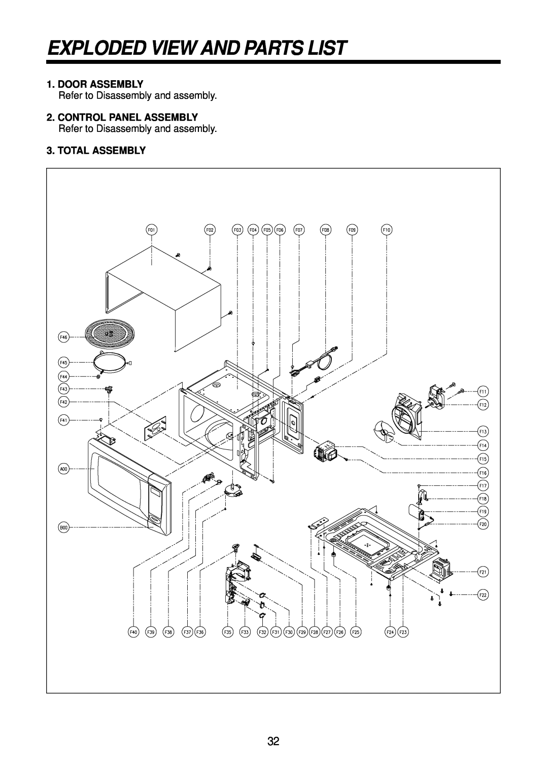
EXPLODED VIEW AND PARTS LIST
1.
DOOR ASSEMBLY
Refer to Disassembly and assembly.
2.
CONTROL PANEL ASSEMBLY
Refer to Disassembly and assembly.
3.
TOTAL ASSEMBLY
32
Page 32
Page 34
Page 33
Image 33
Page 32
Page 34
Contents
Microwave Oven
Service Manual
S/M No. R631G0A003
Model KOR-631G0A KOR-631H0A KOR-631G9A KOR-631H9A KOR-861G0A
TABLE OF CONTENTS
SAFETY AND PRECAUTIONS
2. FOR SAFE SERVICE PROCEDURES
1. FOR SAFE OPERATION
KOR-631G/H
SPECIFICATIONS
KOR-631G/H9A
KOR-861G/H
EXTERNAL VIEW
1. OUTER DIMENSIONKOR-631G/H, 631G/H9/KOR-861G/H
465/495
279/294
6. SAFETY INTERLOCK SYSTEM 7. CONTROL PANEL 8. GLASS COOKING TRAY
2. FEATURE DIAGRAM
1. DOOR SEAL
2. DOOR HOOK
3. CONTROL PANEL
1 KOR-631G0A/631G9A
2 KOR-861G0A
3. CONTROL PANEL
1 KOR-631H0A/631H9A/861H0A
5. Power supply
INSTALLATION
1. Steady, flat location
2. Leave space behind and side
Touch POWER pad
Wattage output chart
Power levelDisplay
Approximate Percentage of Power
Cautions to be observed when trouble shooting
DISASSEMBLY AND ASSEMBLY
1. To remove cabinet
2. To remove door assembly
2 Remove the door assembly from top plate of cavity
3 Reverse the above for reassembly
REF NO
3. To remove door parts
PART CODE
PART NAME
1 Remove the gasket door from door weld as
REF NO
5. To remove control panel parts
PART CODE
PART NAME
6. To remove high voltage capacitor
High voltage circuit wiring 7. To remove magnetron
9. To remove H.V.transformer
8. To remove wind guide assembly
ADJUSTMENT
INTERLOCK MECHANISM AND ADJUSTMENT
TROUBLE SHOOTING GUIDE
Check continuity of interlock
Defective high voltage trans- former
plied to RELAY RY2 coil
TROUBLE 3 No microwave oscillation even though fan motor rotates
1. Incomplete segments 1 Segments missing 2 Partical segments missing
1. MEASUREMENT OF THE MICROWAVE POWER OUTPUT
PROCEDURE
MEASUREMENT AND TEST
2. MICROWAVE RADIATION TEST
PROCEDURES
1. High voltage transformer
3. COMPONENT TEST PROCEDURE
2. High voltage capacitor
3. High voltage diode
WIRING DIAGRAM
PRINTED CIRCUIT BOARD
1. CIRCUIT CHECK PROCEDURE
1. Low Voltage Transformer check
2. Voltage check
Measure Point
5. When the digital clock does not operate properly
3. When there is no microwave oscillation
STATE
POINT
1 KOR-631G0A/631H0A/631H9A/631G9A
2. PCB CIRCUIT DIAGRAM
SPECIFICATION
SYMBOL
3. P.C.B. LOCATION NO
NAME
SPECIFICATION
SYMBOL
NAME
PART CODE
1. DOOR ASSEMBLY
EXPLODED VIEW AND PARTS LIST
Refer to Disassembly and assembly
3. TOTAL ASSEMBLY
PART CODE
PART NAME
DESCRIPTION
PART CODE
PART NAME
DESCRIPTION
PART CODE
PART NAME
DESCRIPTION
PART CODE
PART NAME
DESCRIPTION
PRINTED DATE Aug
S/M NO. R631G0A003
686, AHYEON-DONG MAPO-GU SEOUL, KOREA C.P.O. BOX 8003 SEOUL, KOREA
TELEX DWELEC K28177-8 CABLE “DAEWOOELEC”