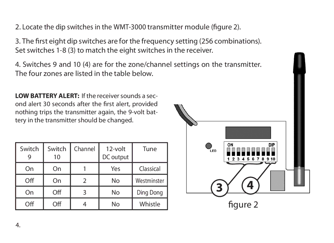
2.Locate the dip switches in the
3.The first eight dip switches are for the frequency setting (256 combinations). Set switches
4.Switches 9 and 10 (4) are for the zone/channel settings on the transmitter. The four zones are listed in the table below.
LOW BATTERY ALERT: If the receiver sounds a sec- ond alert 30 seconds after the first alert, provided nothing trips the transmitter again, the
Switch | Switch | Channel |
| Tune |
9 | 10 |
| DC output |
|
|
|
|
|
|
On | On | 1 | Yes | Classical |
|
|
|
|
|
Off | On | 2 | No | Westminster |
|
|
|
|
|
On | Off | 3 | No | Ding Dong |
|
|
|
|
|
Off | Off | 4 | No | Whistle |
|
|
|
|
|
{ {
3 4
figure 2
4.