650360 specifications
Dakota Digital 650360 is an advanced instrument cluster that has garnered attention among automotive enthusiasts and professionals alike for its innovative features and cutting-edge technologies. Designed primarily for classic vehicles, the 650360 model combines modern functionality with a classic aesthetic, making it a popular choice for those looking to upgrade their dashboards while maintaining a vintage look.One of the standout features of the Dakota Digital 650360 is its high-visibility LED display. The instrument cluster is engineered with bright, vivid LEDs that ensure excellent visibility in various lighting conditions. Whether driving during the day or at night, the display provides clear readings, allowing drivers to monitor their vehicle's performance and status with ease.
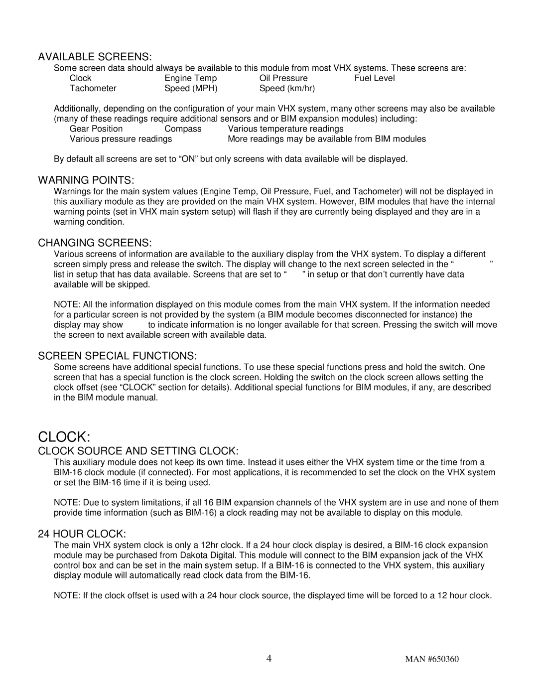
The Dakota Digital 650360 is equipped with a range of digital readouts that cover essential information such as speed, RPM, fuel level, temperature, and oil pressure. These readouts can be customized to suit the driver's preferences, offering flexibility and personalization in the driving experience. The system includes a built-in speedometer and tachometer, along with various warning indicators that help ensure safe operation.
Another key characteristic of the 650360 model is its user-friendly interface. The cluster features intuitive controls that allow users to navigate through the different settings and configurations easily. This simplicity is complemented by comprehensive instructions, making installation and operation a straightforward process for users of all skill levels.
In terms of technology, Dakota Digital utilizes advanced microprocessor-based technology in the 650360, ensuring accurate readings and reliable performance. The cluster is also designed to be compatible with most vehicle types, making it a versatile option for a broad range of applications. Its flexible wiring system allows for seamless integration into classic vehicles while retaining the vehicle's original charm.
Additionally, the Dakota Digital 650360 supports various sensors and communication protocols, enhancing its functionality. This cluster can often connect with aftermarket performance modules, providing drivers with even more data and insights about their vehicle's performance.
In summary, the Dakota Digital 650360 is a modern solution for classic vehicles, boasting high-quality displays, customizable features, and advanced technology that together create an impressive instrument cluster. It is an ideal choice for those looking to enhance their driving experience while preserving the character of their vehicle.
