Wiring: |
|
|
BLACK | - | connect to a good ground point in the vehicle. |
RED | - | connect to switched 12 volt power point. |
|
| (An accessory terminal will work for this.) |
ORANGE | - | connect to a constant 12 volt power point. |
|
| (This will keep the correct time.) |
BLUE | - | connect to the tail light circuit. |
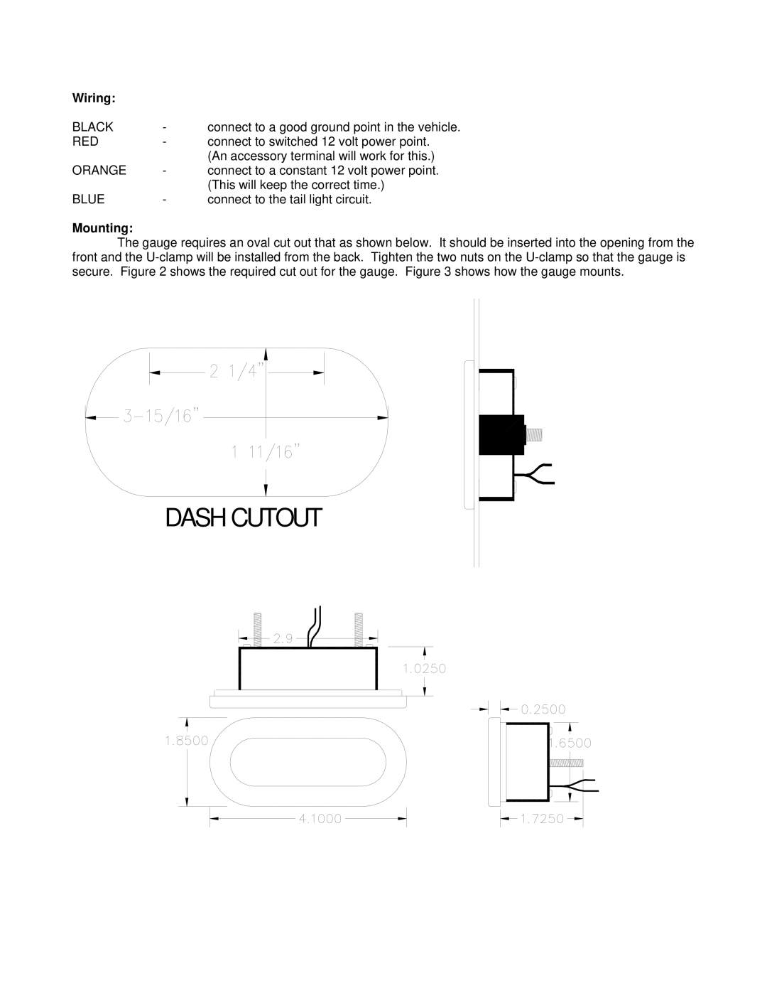
Mounting:
The gauge requires an oval cut out that as shown below. It should be inserted into the opening from the front and the