OPERATING INSTRUCTIONS
Please use the unit between
CONTROL PANEL
INSTRUCTIONS
![]()
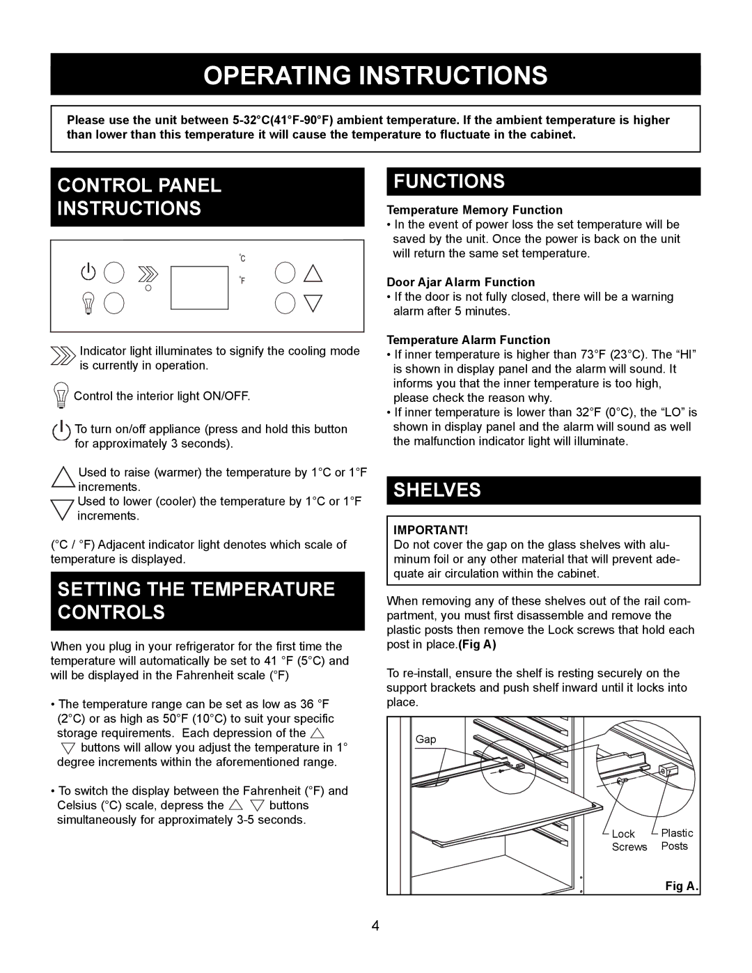
![]() Indicator light illuminates to signify the cooling mode
Indicator light illuminates to signify the cooling mode ![]()
![]() is currently in operation.
is currently in operation.
Control the interior light ON/OFF. |
![]()
![]()
![]()
![]() To turn on/off appliance (press and hold this button
To turn on/off appliance (press and hold this button ![]()
![]()
![]() for approximately 3 seconds).
for approximately 3 seconds).
Used to raise (warmer) the temperature by 1°C or 1°F increments.
Used to lower (cooler) the temperature by 1°C or 1°F increments.
(°C / °F) Adjacent indicator light denotes which scale of temperature is displayed.
SETTING THE TEMPERATURE CONTROLS
When you plug in your refrigerator for the first time the temperature will automatically be set to 41 °F (5°C) and will be displayed in the Fahrenheit scale (°F)
•The temperature range can be set as low as 36 °F (2°C) or as high as 50°F (10°C) to suit your specific storage requirements. Each depression of the ![]()
![]() buttons will allow you adjust the temperature in 1° degree increments within the aforementioned range.
buttons will allow you adjust the temperature in 1° degree increments within the aforementioned range.
•To switch the display between the Fahrenheit (°F) and
Celsius (°C) scale, depress the ![]()
![]() buttons simultaneously for approximately
buttons simultaneously for approximately
FUNCTIONS
Temperature Memory Function
•In the event of power loss the set temperature will be saved by the unit. Once the power is back on the unit will return the same set temperature.
Door Ajar Alarm Function
•If the door is not fully closed, there will be a warning alarm after 5 minutes.
Temperature Alarm Function
•If inner temperature is higher than 73°F (23°C). The “HI” is shown in display panel and the alarm will sound. It informs you that the inner temperature is too high, please check the reason why.
•If inner temperature is lower than 32°F (0°C), the “LO” is shown in display panel and the alarm will sound as well the malfunction indicator light will illuminate.
SHELVES
IMPORTANT!
Do not cover the gap on the glass shelves with alu- minum foil or any other material that will prevent ade- quate air circulation within the cabinet.
When removing any of these shelves out of the rail com- partment, you must first disassemble and remove the plastic posts then remove the Lock screws that hold each post in place.(Fig A)
To
Gap
![]()
![]()
![]() Lock Plastic
Lock Plastic
Screws Posts
Fig A.
4
