|
|
|
| dbx 160A COMPRESSOR / LIMITER | ||||
“MASTER” |
| “SLAVE” | ||||||
|
|
|
|
|
|
|
|
|
160A |
| 160A | ||||||
INPUT OUTPUT | INPUT OUTPUT |
STEREO | STEREO |
STRAPPING | STRAPPING |
TO RIGHT INPUT | TO LEFT INPUT |
FROM RIGHT OUTPUT | FROM LEFT OUTPUT |
TRS “STEREO” CABLE (Shield plus two conductors)
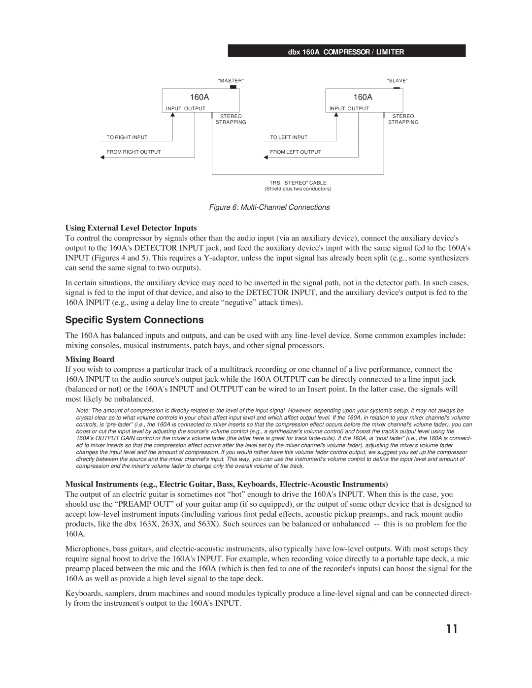
Figure 6: Multi-Channel Connections
Using External Level Detector Inputs
To control the compressor by signals other than the audio input (via an auxiliary device), connect the auxiliary device's output to the 160A's DETECTOR INPUT jack, and feed the auxiliary device's input with the same signal fed to the 160A's INPUT (Figures 4 and 5). This requires a
In certain situations, the auxiliary device may need to be inserted in the signal path, not in the detector path. In such cases, signal is fed to the input of that device, and also to the DETECTOR INPUT, and the auxiliary device's output is fed to the 160A INPUT (e.g., using a delay line to create ÒnegativeÓ attack times).
Specific System Connections
The 160A has balanced inputs and outputs, and can be used with any
Mixing Board
If you wish to compress a particular track of a multitrack recording or one channel of a live performance, connect the 160A INPUT to the audio source's output jack while the 160A OUTPUT can be directly connected to a line input jack (balanced or not) or the 160A's INPUT and OUTPUT can be wired to an Insert point. In the latter case, the signals will most likely be unbalanced.
Note: The amount of compression is directly related to the level of the input signal. However, depending upon your system's setup, it may not always be crystal clear as to what volume controls in your chain affect input level and which affect output level. If the 160A, in relation to your mixer channel's volume controls, is
Musical Instruments (e.g., Electric Guitar, Bass, Keyboards,
The output of an electric guitar is sometimes not ÒhotÓ enough to drive the 160A's INPUT. When this is the case, you should use the ÒPREAMP OUTÓ of your guitar amp (if so equipped), or the output of some other device that is designed to accept
Microphones, bass guitars, and
Keyboards, samplers, drum machines and sound modules typically produce a
11