CENTER CHANNEL
FT6C
When using the FT6C as a center channel speaker in a home theater application the following guidelines should be used for optimum performance.
Locate the speaker as close to the center of your TV or monitor as possible (Figure 1). This will anchor the central image of your home theater to the location of the images seen on the screen.
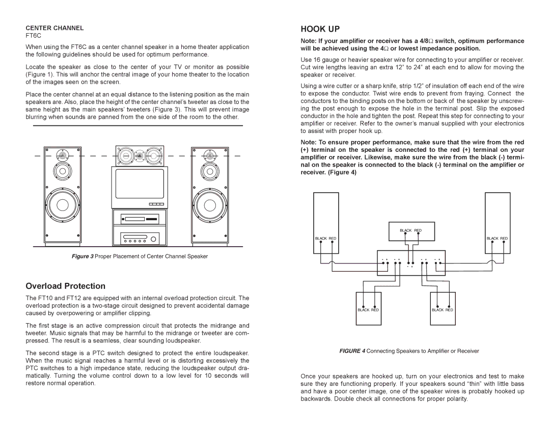
Place the center channel at an equal distance to the listening position as the main speakers are. Also, place the height of the center channel’s tweeter as close to the same height as the main speakers’ tweeters (Figure 3). This will prevent image blurring when sounds are panned from the one side of the room to the other.
Figure 3 Proper Placement of Center Channel Speaker
Overload Protection
The FT10 and FT12 are equipped with an internal overload protection circuit. The overload protection is a
The first stage is an active compression circuit that protects the midrange and tweeter. Music signals that may be harmful to the midrange or tweeter are com- pressed. The result is a seamless, clear sounding loudspeaker.
The second stage is a PTC switch designed to protect the entire loudspeaker. When the music signal reaches a harmful level or is distorting excessively the PTC switches to a high impedance state, reducing the loudspeaker output dra- matically. Turning the volume control down to a low level for 10 seconds will restore normal operation.
HOOK UP
Note: If your amplifier or receiver has a 4/8Ω switch, optimum performance will be achieved using the 4Ω or lowest impedance position.
Use 16 gauge or heavier speaker wire for connecting to your amplifier or receiver. Cut wire lengths leaving an extra 12” to 24” at each end to allow for moving the speaker or receiver.
Using a wire cutter or a sharp knife, strip 1/2” of insulation off each end of the wire to expose the conductor. Twist wire ends to prevent from fraying. Connect the conductors to the binding posts on the bottom or back of the speaker by unscrew- ing the post enough to expose the hole in the terminal post. Slip the exposed conductor in the hole and tighten the post. Repeat this step for connecting to your amplifier or receiver. Refer to the owner’s manual supplied with your electronics to assist with proper hook up.
Note: To ensure proper performance, make sure that the wire from the red
(+)terminal on the speaker is connected to the red (+) terminal on your amplifier or receiver. Likewise, make sure the wire from the black
| BLACK RED |
BLACK RED | BLACK RED |
- + | - + | - + | - + |
-+
BLACK RED | BLACK RED |
FIGURE 4 Connecting Speakers to Amplifier or Receiver
Once your speakers are hooked up, turn on your electronics and test to make sure they are functioning properly. If your speakers sound “thin” with little bass and have a poor center image, one of the speaker wires is probably hooked up backwards. Double check all connections for proper polarity.