EXPLANATION OF FEATURES AND CONTROLS
Refer to figure A.
1)Polarity switch: This two position switch allows the best match of acoustic output between the subwoofer and the main stereo speakers in the region of the crossover frequency between them. The “normal” position maintains phase from input to output, the “reverse” position changes polarity or phase by 180 degrees.
2)Power switch: This three position switch controls the power status of the subwoofer.
Off: Turns the unit off.
Auto: Places the unit in the standby mode, in this mode the subwoofer will automatically turn on when an audio signal is applied to either the high or low level inputs.
On: Turns the unit on regardless of whether a signal is present or not.
3)Subwoofer crossover : This rotary control adjusts a variable low pass filter to set the upper frequency at which the output of the subwoofer begins to
4)Line level output: These RCA phono jacks provide a line level, stereo output of the full range signal input. This output is provided for those wishing to “bi- amplify” their main stereo speakers.
5)Line level input: These RCA phono jacks accept a line level full range signal from the preamplifier output of a receiver or preamplifier. This full range signal is processed and amplified to power the subwoofer.
6)Speaker level input: These terminals for speaker wire accept a stereo, speaker level, full range signal from a receiver or power amplifier. This signal is processed and amplified to power the subwoofer.
7)Fuse: For continued protection replace fuse with same type and size listed.
8)Level control: This rotary control adjusts the level of the subwoofer and is used to balance its volume with that of the main stereo speakers.
9)Status LED: This two color light emitting diode shows the status of the subwoofer electronics. “Red” indicates that the amplifier is plugged in and the power switch is either off or in standby mode with no input signal present. “Green” indicates that the amplifier is operating with signal present at the input from the preamplifier, receiver, or power amplifier.
Installation using line level inputs
A) Using a preamp or receiver with line level outputs.
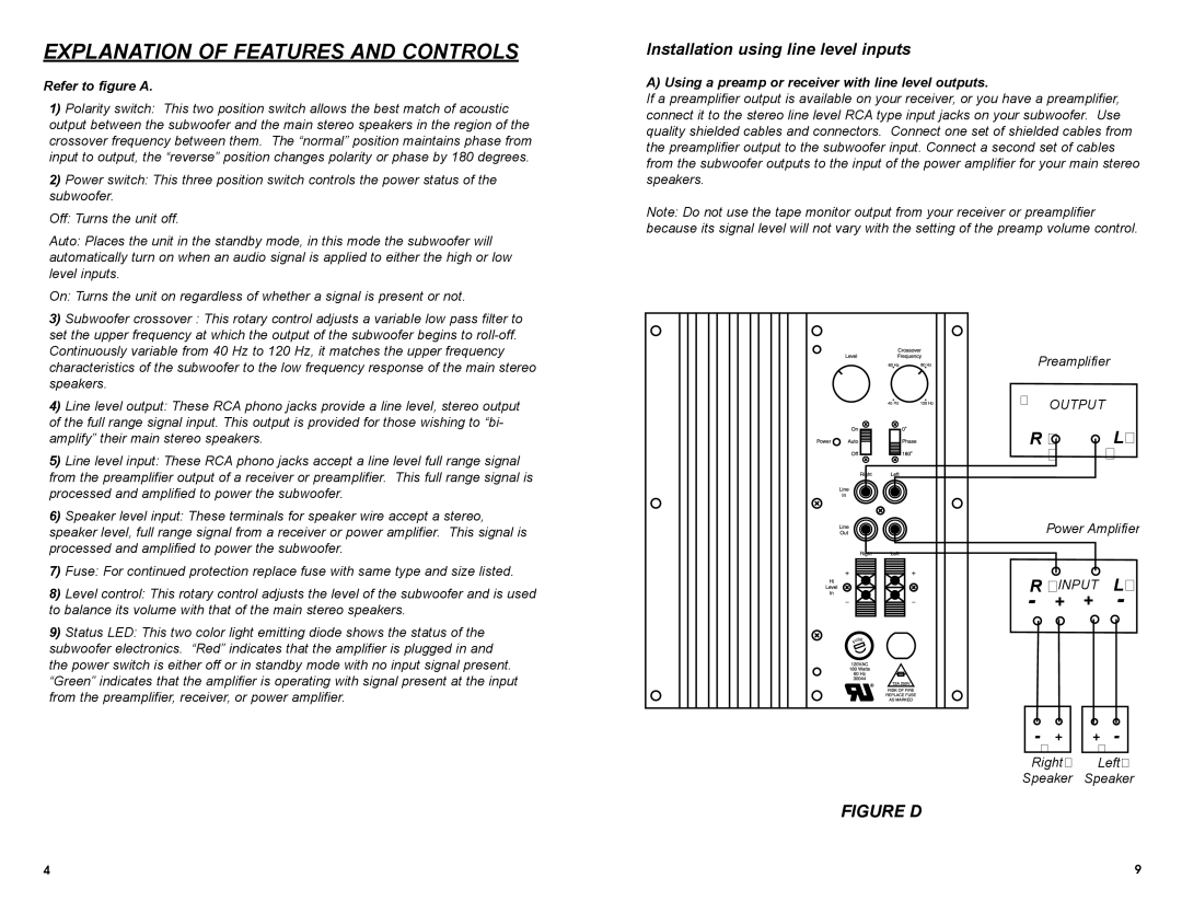
If a preamplifier output is available on your receiver, or you have a preamplifier, connect it to the stereo line level RCA type input jacks on your subwoofer. Use quality shielded cables and connectors. Connect one set of shielded cables from the preamplifier output to the subwoofer input. Connect a second set of cables from the subwoofer outputs to the input of the power amplifier for your main stereo speakers.
Note: Do not use the tape monitor output from your receiver or preamplifier because its signal level will not vary with the setting of the preamp volume control.
Preamplifier
� OUTPUT
R � | L� |
� | � |
Power Amplifier
R �INPUT L�
- + + -
- | + | + | - |
� |
| � |
|
Right� | Left� | ||
Speaker | Speaker | ||
FIGURE D
4 | 9 |