BI-CÂBLAGE ET BI-AMPLIFICATION
Si vous décidez d’effectuer un
Le
La
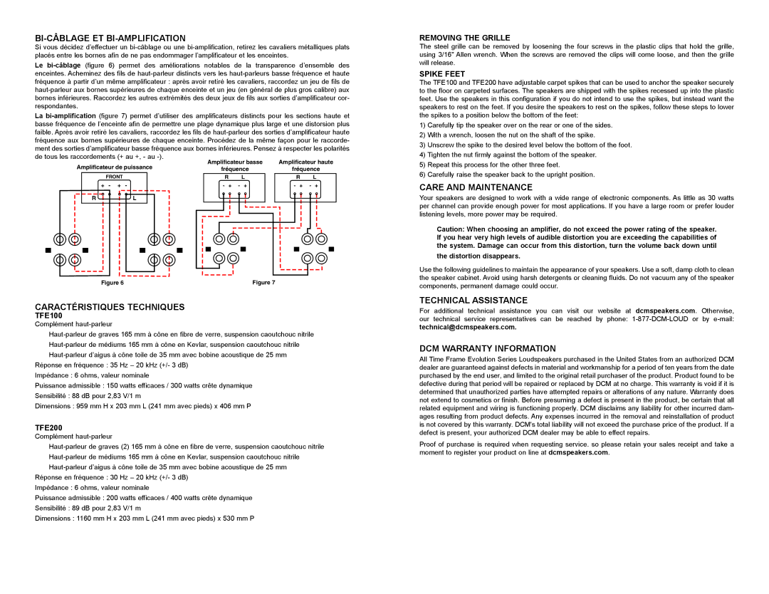
de tous les raccordements (+ au +, - au | Amplificateur basse | Amplificateur haute | ||||
Amplificateur de puissance | ||||||
fréquence | fréquence | |||||
|
| |||||
FRONT | R | L | R | L | ||
+ - | + - | - + - + | - + - + | |||
RL
+ | + | + | + |
Figure 6 |
|
| Figure 7 |
CARACTÉRISTIQUES TECHNIQUES
TFE100
Complément
Réponse en fréquence : 35 Hz – 20 kHz (+/- 3 dB)
Impédance : 6 ohms, valeur nominale
Puissance admissible : 150 watts efficaces / 300 watts crête dynamique
Sensibilité : 88 dB pour 2,83 V/1 m
Dimensions : 959 mm H x 203 mm L (241 mm avec pieds) x 406 mm P
TFE200
Complément
Réponse en fréquence : 30 Hz – 20 kHz (+/- 3 dB)
Impédance : 6 ohms, valeur nominale
Puissance admissible : 200 watts efficaces / 400 watts crête dynamique
Sensibilité : 89 dB pour 2,83 V/1 m
Dimensions : 1160 mm H x 203 mm L (241 mm avec pieds) x 530 mm P
REMOVING THE GRILLE
The steel grille can be removed by loosening the four screws in the plastic clips that hold the grille, using 3/16" Allen wrench. When the screws are removed the clips will come loose, and then the grille will release.
SPIKE FEET
The TFE100 and TFE200 have adjustable carpet spikes that can be used to anchor the speaker securely to the floor on carpeted surfaces. The speakers are shipped with the spikes recessed up into the plastic feet. Use the speakers in this configuration if you do not intend to use the spikes, but instead want the speakers to rest on the feet. If you desire the speakers to rest on the spikes, follow these steps to lower the spikes to a position below the bottom of the feet:
1)Carefully tip the speaker over on the rear or one of the sides.
2)With a wrench, loosen the nut on the shaft of the spike.
3)Unscrew the spike to the desired level below the bottom of the foot.
4)Tighten the nut firmly against the bottom of the speaker.
5)Repeat this process for the other three feet.
6)Carefully raise the speaker back to the upright position.
CARE AND MAINTENANCE
Your speakers are designed to work with a wide range of electronic components. As little as 30 watts per channel can provide enough power for most applications. If you have a large room or prefer louder listening levels, more power may be required.
Caution: When choosing an amplifier, do not exceed the power rating of the speaker. If you hear very high levels of audible distortion you are exceeding the capabilities of the system. Damage can occur from this distortion, turn the volume back down until
the distortion disappears.
Use the following guidelines to maintain the appearance of your speakers. Use a soft, damp cloth to clean the speaker cabinet. Avoid using harsh detergents or cleaning fluids. Do not vacuum any of the speaker components, permanent damage could occur.
TECHNICAL ASSISTANCE
For additional technical assistance you can visit our website at dcmspeakers.com. Otherwise, our technical service representatives can be reached by phone:
DCM WARRANTY INFORMATION
All Time Frame Evolution Series Loudspeakers purchased in the United States from an authorized DCM dealer are guaranteed against defects in material and workmanship for a period of ten years from the date purchased by the end user, and limited to the original retail purchaser of the product. Product found to be defective during that period will be repaired or replaced by DCM at no charge. This warranty is void if it is determined that unauthorized parties have attempted repairs or alterations of any nature. Warranty does not extend to cosmetics or finish. Before presuming a defect is present in the product, be certain that all related equipment and wiring is functioning properly. DCM disclaims any liability for other incurred dam- ages resulting from product defects. Any expenses incurred in the removal and reinstallation of product is not covered by this warranty. DCM's total liability will not exceed the purchase price of the product. If a defect is present, your authorized DCM dealer may be able to effect repairs.
Proof of purchase is required when requesting service. so please retain your sales receipt and take a moment to register your product on line at dcmspeakers.com.