SPECIFICATIONS
B
A
B
A
![]() 8-3/4
8-3/4![]()
12 "
![]()
![]()
![]()
![]()
MODEL | A |
| B | RACK | RACK | |
|
|
|
|
| ||
|
|
|
|
| QTY. | QTY. |
|
|
|
|
| ||
- | - | |||||
|
|
|
|
|
| |
29 | 2 | - | ||||
35 | 10 | - | - | |||
28 | - | 2 | ||||
10 | - | - | ||||
2 | 1 | |||||
|
|
|
|
|
|
|
WALL MOUNT LOW BACKGUARD INSTALLATION
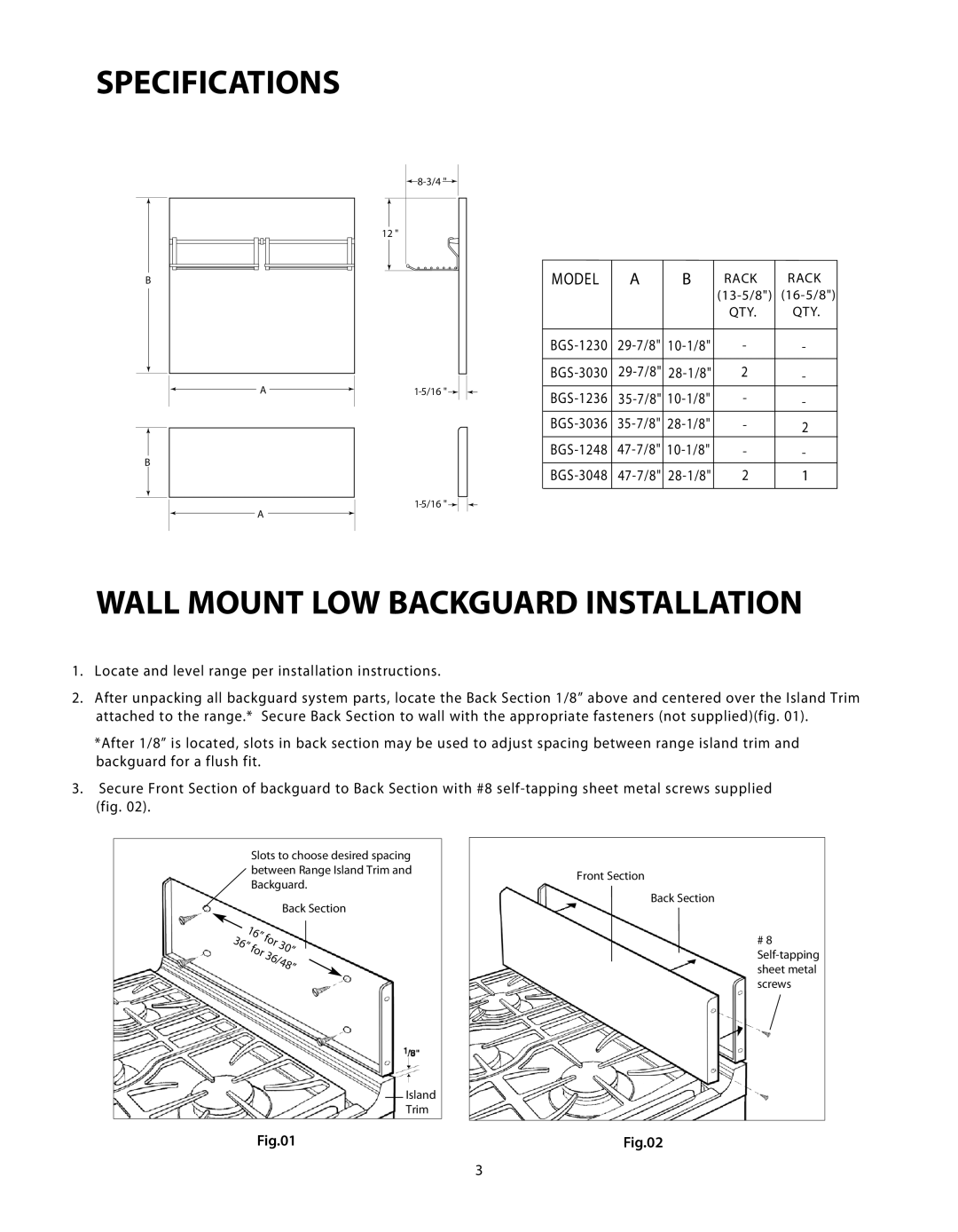
1.Locate and level range per installation instructions.
2.After unpacking all backguard system parts, locate the Back Section 1/8” above and centered over the Island Trim attached to the range.* Secure Back Section to wall with the appropriate fasteners (not supplied)(fig. 01).
*After 1/8” is located, slots in back section may be used to adjust spacing between range island trim and backguard for a flush fit.
3.Secure Front Section of backguard to Back Section with #8
(fig. 02).
Slots to choose desired spacing between Range Island Trim and Backguard.
|
|
|
|
| Back Section |
|
| ” |
|
|
|
|
|
|
|
| |
|
| 16 | r |
|
|
| ” |
| ” | ||
3 | 6 | r | fo |
| |
|
| 30” | |||
|
| fo | /48 | ||
|
|
| 36 |
|
|
Island
Trim
Fig.01
Front Section
Back Section
# 8
Fig.02
3