\
505710 / 505628 Series User’s Manual
3.2 Front Panel LEDs
LED | Color | Status | Description | |
PWR1 | Green | On | DC power module 1 activated. | |
|
|
|
| |
PWR2 | Green | On | DC power module 2 activated. | |
|
|
|
| |
Fault | Amber | On | Fault relay. Power failure. | |
|
|
|
| |
| ||||
|
|
|
| |
LNK / ACT | Green | On | Port link up. | |
|
| |||
Blinking | Data transmitted. | |||
|
| |||
|
|
|
| |
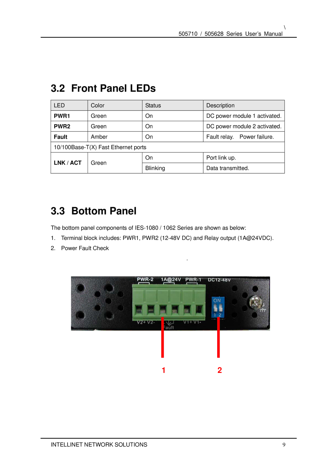
3.3 Bottom Panel
The bottom panel components of
1.Terminal block includes: PWR1, PWR2
2.Power Fault Check
.
12
INTELLINET NETWORK SOLUTIONS | 9 |