11.Thoroughly clean the knife slots, knife locking bars, and locking screws. Check the screws; if the threads appear worn or stripped, or if the heads are damaged, replace them.
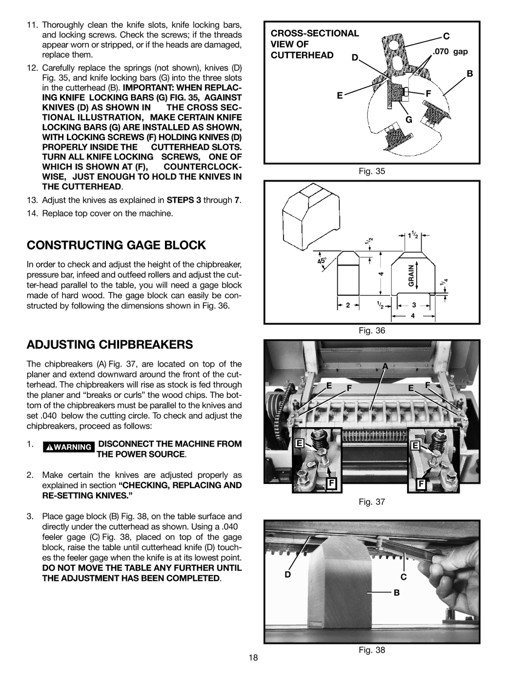
12.Carefully replace the springs (not shown), knives (D) Fig. 35, and knife locking bars (G) into the three slots in the cutterhead (B). IMPORTANT: WHEN REPLAC-
ING KNIFE LOCKING BARS (G) FIG. 35, AGAINST
KNIVES (D) AS SHOWN IN | THE CROSS SEC- |
TIONAL ILLUSTRATION, MAKE CERTAIN KNIFE | |
LOCKING BARS (G) ARE INSTALLED AS SHOWN, | |
WITH LOCKING SCREWS (F) HOLDING KNIVES (D) | |
PROPERLY INSIDE THE | CUTTERHEAD SLOTS. |
TURN ALL KNIFE LOCKING SCREWS, ONE OF | |
WHICH IS SHOWN AT (F), | COUNTERCLOCK- |
WISE, JUST ENOUGH TO HOLD THE KNIVES IN THE CUTTERHEAD.
13.Adjust the knives as explained in STEPS 3 through 7.
14.Replace top cover on the machine.
CONSTRUCTING GAGE BLOCK
In order to check and adjust the height of the chipbreaker, pressure bar, infeed and outfeed rollers and adjust the cut-
ADJUSTING CHIPBREAKERS
The chipbreakers (A) Fig. 37, are located on top of the planer and extend downward around the front of the cut- terhead. The chipbreakers will rise as stock is fed through the planer and “breaks or curls” the wood chips. The bot- tom of the chipbreakers must be parallel to the knives and set .040 below the cutting circle. To check and adjust the chipbreakers, proceed as follows:
1. |
|
|
| DISCONNECT THE MACHINE FROM |
|
|
| ||
|
|
| ||
|
|
|
| THE POWER SOURCE. |
|
|
|
|
2.Make certain the knives are adjusted properly as explained in section “CHECKING, REPLACING AND
RE-SETTING KNIVES.”
3.Place gage block (B) Fig. 38, on the table surface and directly under the cutterhead as shown. Using a .040 feeler gage (C) Fig. 38, placed on top of the gage block, raise the table until cutterhead knife (D) touch- es the feeler gage when the knife is at its lowest point.
DO NOT MOVE THE TABLE ANY FURTHER UNTIL THE ADJUSTMENT HAS BEEN COMPLETED.
C | |||
VIEW OF |
| ||
| .070 gap | ||
CUTTERHEAD | D | ||
| |||
|
| B | |
E |
| F | |
|
| G | |
Fig. 35
2 | 11/2 |
|
/ |
|
|
1 |
|
|
4 | GRAIN | 1 |
|
| 4 |
|
| / |
2 1/23
4
Fig. 36
A
E FE F
E | E |
F | F |
Fig. 37
DC
B
Fig. 38
18