SMT Couple Inductor
DHCB Type
Features
RoHS compliant.
Low profile, SMD type.
High current.
Magnetic shielded.
High energy storage and low DCR.
Provided with embossed carrier tape packing.
Ideal for power source circuits,
In addition to the standard versions shown here, customized inductors
are available to meet your exact requirements.
RECOMMENDED PAD PATTERNS
B | C | F | |
4 | 3 |
| |
A |
| E | |
1 | 2 | D | |
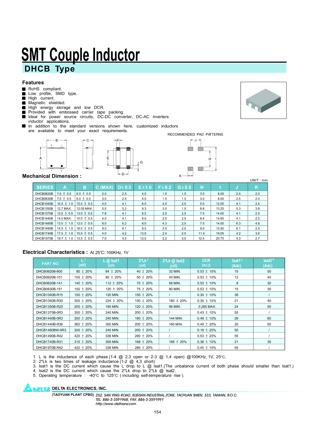
Mechanical Dimension : | |||
| |||
![]() J
J ![]()
H I
![]() G
G
K
|
|
|
|
|
|
|
|
|
|
|
|
| UNIT : mm |
SERIES |
| A |
| B | C (MAX) | D 0.5 | E 1.0 | F 0.2 | G 0.5 | H | I | J | K |
DHCB0620B | 7.0 | 0.5 | 6.0 | 0.5 | 2.0 | 2.5 | 4.0 | 1.5 | 1.5 | 3.0 | 8.00 | 2.5 | 2.0 |
DHCB0630B | 7.0 | 0.5 | 6.0 | 0.5 | 3.0 | 2.5 | 4.0 | 1.5 | 1.5 | 3.0 | 8.00 | 2.5 | 2.0 |
DHCB1040B | 10.5 | 1.0 | 10.0 | 0.5 | 4.0 | 4.1 | 6.0 | 2.0 | 2.5 | 5.0 | 12.00 | 4.1 | 2.5 |
DHCB1350B | 12.7 MAX. | 12.05 MAX. | 5.0 | 5.3 | 9.3 | 3.0 | 1.5 | 8.8 | 13.20 | 5.3 | 3.8 | ||
DHCB1375B | 13.0 | 0.5 | 13.0 | 0.5 | 7.8 | 4.1 | 8.0 | 2.0 | 2.5 | 7.5 | 14.00 | 4.1 | 2.5 |
DHCB1440B | 14.0 MAX. | 10.0 | 0.5 | 4.0 | 4.1 | 8.0 | 2.0 | 2.5 | 8.4 | 14.60 | 4.1 | 2.5 | |
DHCB1480B | 13.0 | 1.0 | 12.0 | 0.5 | 8.0 | 6.3 | 8.0 | 4.3 | 2.5 | 7.5 | 14.00 | 6.3 | 4.8 |
DHCB1490B | 14.5 | 1.0 | 16.0 | 0.5 | 9.0 | 6.1 | 9.5 | 2.0 | 2.5 | 9.0 | 15.50 | 6.1 | 2.5 |
DHCB1740B | 17.0 | 1.0 | 10.0 | 0.5 | 4.0 | 4.2 | 13.0 | 2.4 | 2.0 | 11.4 | 19.05 | 4.2 | 3.6 |
DHCB1970B | 19.7 | 1.0 | 13.5 | 0.5 | 7.0 | 5.3 | 13.5 | 2.2 | 3.0 | 12.5 | 20.70 | 5.3 | 2.7 |
Electrical Characteristics : At 25oC: 100KHz, 1V
PART NO. |
| L 1 |
(nH) | ||
80 | 20% | |
100 | 20% | |
140 | 20% | |
150 | 20% | |
150 | 20% | |
300 | 20% | |
200 | 20% | |
300 | 20% | |
300 | 20% | |
360 | 20% | |
300 | 20% | |
420 | 20% | |
310 | 20% | |
420 | 20% | |
L @ Isat1 | 2*Lk 2 | 2*Lk @ Isat2 | DCR | |||||
(nH) |
| (nH) |
|
| (nH) |
| (m | ) |
64 | 20% | 40 | 20% |
| 32 MIN. | 0.53 | 10% | |
80 | 20% | 50 | 20% |
| 40 MIN. | 0.53 | 10% | |
112 | 20% | 70 | 20% |
| 56 MIN. | 0.53 | 10% | |
120 | 20% | 75 | 20% |
| 80 MIN. | 0.53 | 10% | |
120 MIN. | 150 | 20% |
| / |
| 0.30 | 10% | |
224 | 20% | 150 | 20% |
| 180 | 20% | 0.30 | 10% |
160 MIN. | 120 | 20% |
| 96 MIN. | 0.265 MAX. | |||
240 MIN. | 200 | 20% |
| / |
| 0.43 | 10% | |
240 MIN. | 180 | 20% |
| 144 MIN. | 0.49 | 10% | ||
300 MIN. | 200 | 20% |
| 160 MIN. | 0.49 | 20% | ||
240 MIN. | 200 | 20% |
| / |
| 0.18 | 20% | |
336 MIN. | 280 | 20% |
| / |
| 0.53 | 20% | |
300 MIN. | 168 | 20% |
| 168 | 20% | 0.38 | 10% | |
336 MIN. | 280 | 20% |
| / |
| 0.45 | 10% | |
Isat13 | Isat2 4 |
(Adc) | (Adc) |
15 | 50 |
12 | 40 |
8 | 30 |
15 | 30 |
38 | / |
21 | 40 |
24 | 50 |
55 | / |
26 | 60 |
20 | 55 |
50 | / |
55 | / |
21 | 35 |
55 | / |
1. | L is the inductance of each phase |
2. | 2*Lk is two times of leakage inductance |
3.Isat1 is the DC current which cause the L drop to L @ lsat1.(The unbalance current of both phase should smaller than Isat1.)
4.Isat2 is the DC current which cause the 2*Lk drop to 2*Lk @ lsat2.
5.Operating temperature :
DELTA ELECTRONICS, INC.
(TAOYUAN PLANT CPBG) 252, SAN YING ROAD, KUEISAN INDUSTRIAL ZONE, TAOYUAN SHIEN, 333, TAIWAN, R.O.C.
TEL:
http://www.deltaww.com
154