http://www.delta.com.tw/industrialautomation/
Extension Digital I/O Module
Instruction Sheet
Warning
3Please read this instruction carefully before use.
3DOP series Extension Digital I/O Module should be used with
3Please install this DOP series Extension Digital I/O Module in an enclosure free of airborne dust, humidity, electric shock and vibration. The enclosure should prevent
3DO NOT connect input AC power supply to any of the I/O terminals; otherwise serious damage may occur. Check all the wiring again before switching on the power.
3DO NOT touch any internal circuit in 1 minute after the power is switched off. Do NOT touch any terminal when the power is switched on.
3Make sure the ground terminal ![]() is correctly grounded in order to prevent electromagnetic interference.
is correctly grounded in order to prevent electromagnetic interference.
3DO NOT place any heavy objects on the connection port of DOP series Extension Digital I/O Module. Doing so may damage the product.
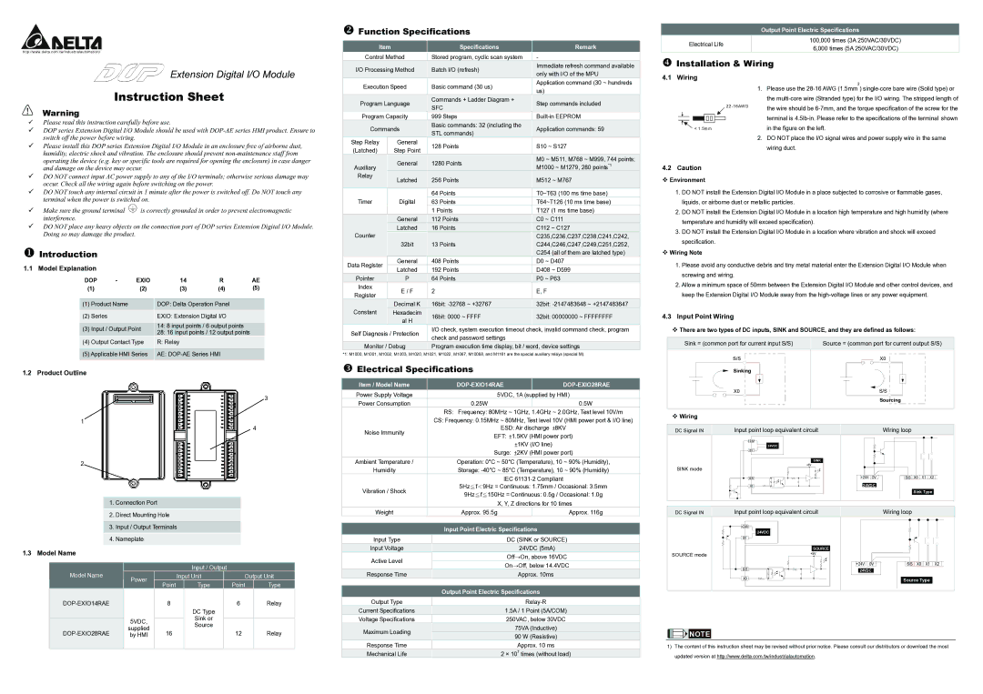
XIntroduction
1.1 | Model Explanation |
|
|
|
|
|
|
| ||
|
| DOP | - | EXIO | 14 | R | AE | |||
| (1) |
| (2) |
| (3) | (4) | (5) | |||
|
|
|
|
|
|
|
|
| ||
|
| (1) | Product Name |
|
|
| DOP: Delta Operation Panel |
| ||
|
|
|
|
|
|
|
|
|
|
|
|
| (2) | Series |
|
|
|
| EXIO: Extension Digital I/O |
| |
|
|
|
|
|
|
|
|
|
| |
|
| (3) | Input / Output Point |
|
| 14: 8 input points / 6 output points |
| |||
|
|
|
| 28: 16 input points / 12 output points |
| |||||
|
|
|
|
|
|
|
|
| ||
|
| (4) | Output Contact Type |
|
| R: Relay |
|
| ||
|
|
|
|
|
|
|
|
|
|
|
|
| (5) Applicable HMI Series |
|
| AE: |
| ||||
|
|
|
|
|
|
|
|
|
|
|
1.2 | Product Outline |
|
|
|
|
|
|
|
| |
3
1
4
2
1.Connection Port
2.Direct Mounting Hole
3.Input / Output Terminals
4.Nameplate
1.3 Model Name
|
|
|
|
|
|
| Input / Output |
|
|
| ||
Model Name |
| Power |
|
| Input Unit |
|
| Output Unit | ||||
|
|
| Point |
|
| Type |
|
| Point |
| Type | |
|
|
|
|
|
|
|
|
| ||||
|
|
| 8 |
|
|
|
|
| 6 |
| Relay | |
|
|
|
|
|
|
| DC Type |
|
|
|
|
|
|
| 5VDC, |
|
|
|
| Sink or |
|
|
|
|
|
|
|
|
|
|
|
|
|
|
|
| ||
|
|
|
|
|
| Source |
|
|
|
|
| |
|
| supplied |
|
|
|
|
|
|
|
|
| |
|
| 16 |
|
|
|
|
| 12 |
| Relay | ||
| by HMI |
|
|
|
|
|
|
| ||||
|
|
|
|
|
|
|
| |||||
|
|
|
|
|
|
|
|
|
|
|
|
|
YFunction Specifications
Item |
|
| Specifications |
| Remark | ||
Control Method |
| Stored program, cyclic scan system |
| - | |||
I/O Processing Method |
| Batch I/O (refresh) |
| Immediate refresh command available | |||
|
| only with I/O of the MPU | |||||
|
|
|
|
|
|
| |
Execution Speed |
| Basic command (30 us) |
| Application command (30 ~ hundreds | |||
|
| us) | |||||
|
|
|
|
|
|
| |
Program Language |
| Commands + Ladder Diagram + |
| Step commands included | |||
| SFC |
| |||||
|
|
|
|
|
|
| |
Program Capacity |
| 999 Steps |
| ||||
Commands |
| Basic commands: 32 (including the |
| Application commands: 59 | |||
| STL commands) |
| |||||
|
|
|
|
|
|
| |
Step Relay |
|
| General |
| 128 Points |
| S10 ~ S127 |
(Latched) |
|
| Step Point |
|
| ||
|
|
|
|
|
| ||
|
|
| General |
| 1280 Points |
| M0 ~ M511, M768 ~ M999, 744 points; |
Auxiliary |
|
|
|
| M1000 ~ M1279, 280 points*1 | ||
|
|
|
|
| |||
Relay |
|
| Latched |
| 256 Points |
| M512 ~ M767 |
|
|
|
|
| |||
|
|
|
|
|
|
|
|
|
|
|
|
| 64 Points |
| T0~T63 (100 ms time base) |
Timer |
|
| Digital |
| 63 Points |
| T64~T126 (10 ms time base) |
|
|
|
|
| 1 Points |
| T127 (1 ms time base) |
|
|
| General |
| 112 Points |
| C0 ~ C111 |
|
|
| Latched |
| 16 Points |
| C112 ~ C127 |
Counter |
|
|
|
|
|
| C235,C236,C237,C238,C241,C242, |
|
|
| 32bit |
| 13 Points |
| C244,C246,C247,C249,C251,C252, |
|
|
|
|
|
|
| C254 (all of them are latched type) |
Data Register |
|
| General |
| 408 Points |
| D0 ~ D407 |
|
| Latched |
| 192 Points |
| D408 ~ D599 | |
|
|
|
|
| |||
Pointer |
|
| P |
| 64 Points |
| P0 ~ P63 |
Index |
|
| E / F |
| 2 |
| E, F |
Register |
|
|
|
| |||
|
|
|
|
|
|
| |
|
|
| Decimal K |
| 16bit: |
| 32bit: |
Constant |
|
| Hexadecim |
| 16bit: 0000 ~ FFFF |
| 32bit: 00000000 ~ FFFFFFFF |
|
|
| al H |
|
| ||
|
|
|
|
|
|
| |
Self Diagnosis / Protection |
| I/O check, system execution timeout check, invalid command check, program | |||||
| check and password settings |
|
| ||||
|
|
|
|
|
|
| |
Monitor / Debug |
| Program execution time display, bit / word, device settings | |||||
*1: M1000, M1001, M1002, M1003, M1020, M1021, M1022, M1067, M10068, and M1161 are the special auxiliary relays (special M).
ZElectrical Specifications
Item / Model Name |
|
|
|
|
|
Power Supply Voltage |
| 5VDC, 1A (supplied by HMI) | |||
Power Consumption |
| 0.25W |
|
| 0.5W |
|
| RS: Frequency: 80MHz ~ 1GHz, 1.4GHz ~ 2.0GHz, Test level 10V/m | |||
|
| CS: Frequency: 0.15MHz ~ 80MHz, Test level 10V (HMI power port & I/O line) | |||
Noise Immunity |
| ESD: Air discharge ±8KV | |||
| EFT: ±1.5KV (HMI power port) | ||||
|
| ||||
|
|
| ±1KV (I/O line) | ||
|
| Surge: ±2KV (HMI power port) | |||
Ambient Temperature / |
| Operation: 0°C ~ 50°C (Temperature), 10 ~ 90% (Humidity), | |||
Humidity |
| Storage: | |||
|
|
| IEC | ||
Vibration / Shock |
| 5Hz≦f<9Hz = Continuous: 1.75mm / Occasional: 3.5mm | |||
| 9Hz≦f≦150Hz = Continuous: 0.5g / Occasional: 1.0g | ||||
|
| ||||
|
| X, Y, Z directions for 10 times | |||
Weight |
| Approx. 95.5g |
|
| Approx. 116g |
|
| Input Point Electric Specifications |
|
| |
Input Type |
| DC (SINK or SOURCE) |
Input Voltage |
| 24VDC (5mA) |
Active Level |
| Off→On, above 16VDC |
| On→Off, below 14.4VDC | |
|
| |
Response Time |
| Approx. 10ms |
|
| Output Point Electric Specifications |
|
| |
Output Type |
| |
Current Specifications |
| 1.5A / 1 Point (5A/COM) |
Voltage Specifications |
| 250VAC, below 30VDC |
Maximum Loading |
| 75VA (Inductive) |
| 90 W (Resistive) | |
|
| |
Response Time |
| Approx. 10 ms |
Mechanical Life |
| 2 × 10⁷ times (without load) |
Output Point Electric Specifications
Electrical Life | 100,000 times (3A 250VAC/30VDC) | |
6,000 times (5A 250VAC/30VDC) | ||
|
[Installation & Wiring
4.1 Wiring
2
1.Please use the
|
|
| the wire should be | |
|
|
|
| |
|
|
|
| terminal is |
|
|
|
| |
|
|
|
| in the figure on the left. |
< 1.5mm |
|
| ||
2.DO NOT place the I/O signal wires and power supply wire in the same wiring duct.
4.2 Caution
Environment
1.DO NOT install the Extension Digital I/O Module in a place subjected to corrosive or flammable gases, liquids, or airborne dust or metallic particles.
2.DO NOT install the Extension Digital I/O Module in a location high temperature and high humidity (where temperature and humidity will exceed specification).
3.DO NOT install the Extension Digital I/O Module in a location where vibration and shock will exceed specification.
Wiring Note
1.Please avoid any conductive debris and tiny metal material enter the Extension Digital I/O Module when screwing and wiring.
2.Allow a minimum space of 50mm between the Extension Digital I/O Module and other control devices, and keep the Extension Digital I/O Module away from the
4.3Input Point Wiring
There are two types of DC inputs, SINK and SOURCE, and they are defined as follows:
Sink = (common port for current input S/S) | Source = (common port for current output S/S) |
S/S | X0 |
Sinking |
|
X0 | S/S |
| Sourcing |
Wiring
DC Signal IN | Input point loop equivalent circuit | Wiring loop | ||
|
|
|
|
|
+24V |
|
|
|
|
| 24VDC |
|
|
|
0V |
|
|
|
|
| SINK |
|
|
|
SINK mode | +5V |
|
|
|
|
|
|
| |
S/S | +24V | OV | S/S | X0 X1 X2 |
X0 | 24VDC |
|
| |
|
|
|
| Sink Type |
DC Signal IN | Input point loop equivalent circuit | Wiring loop |
|
|
|
| +24V |
|
|
|
|
|
| 24VDC |
|
|
|
| 0V |
|
|
|
|
|
| SOURCE |
|
|
|
SOURCE mode |
| +5V |
|
|
|
| S/S | +24V | 0V | S/S X0 X1 | X2 |
| 24VDC |
|
| ||
|
|
|
| ||
| X0 |
|
| Source Type |
|
|
|
|
|
| |
![]()
![]()
![]()
![]() NOTE
NOTE
1)The content of this instruction sheet may be revised without prior notice. Please consult our distributors or download the most updated version at http://www.delta.com.tw/industrialautomation.