Manuals
/
Delta Electronics
/
Computer Equipment
/
Network Card
Delta Electronics
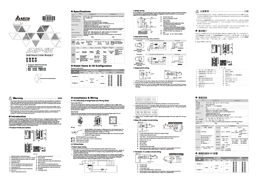
DVP28SV
specifications
產品簡介, 電氣規格, Specifications, 注意事項, Installation & Wiring
Models:
DVP28SV
1
1
1
Download
1 pages
34.4 Kb
1
2
Specs
Page 1
Image 1
Page 1
Page 1
Page 1
Image 1
Page 1
Page 1
Contents
Model Name & I/O Configuration
Specifications
Installation & Wiring
Safety wiring
Top
Page
Image
Contents