LCP-10G3A4EDR
Module Electrical Pin Definition
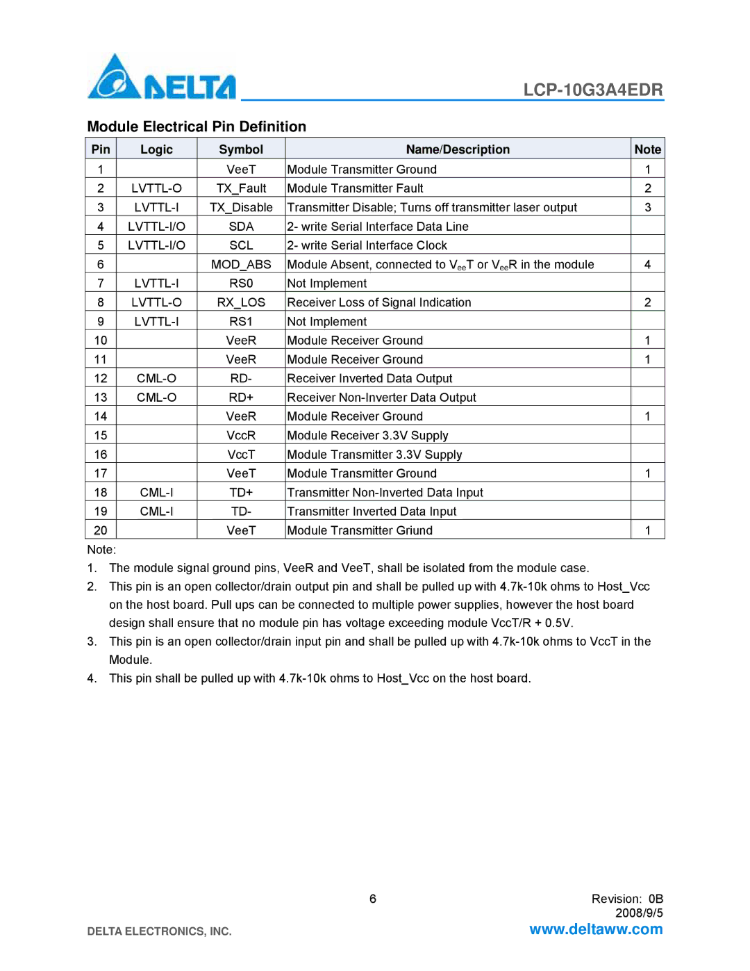
Pin | Logic | Symbol | Name/Description | Note |
1 |
| VeeT | Module Transmitter Ground | 1 |
2 | TX_Fault | Module Transmitter Fault | 2 | |
3 | TX_Disable | Transmitter Disable; Turns off transmitter laser output | 3 | |
4 | SDA | 2- write Serial Interface Data Line |
| |
5 | SCL | 2- write Serial Interface Clock |
| |
6 |
| MOD_ABS | Module Absent, connected to VeeT or VeeR in the module | 4 |
7 | RS0 | Not Implement |
| |
8 | RX_LOS | Receiver Loss of Signal Indication | 2 | |
9 | RS1 | Not Implement |
| |
10 |
| VeeR | Module Receiver Ground | 1 |
11 |
| VeeR | Module Receiver Ground | 1 |
12 | RD- | Receiver Inverted Data Output |
| |
13 |
| RD+ | Receiver |
|
14 |
| VeeR | Module Receiver Ground | 1 |
15 |
| VccR | Module Receiver 3.3V Supply |
|
16 |
| VccT | Module Transmitter 3.3V Supply |
|
17 |
| VeeT | Module Transmitter Ground | 1 |
18 | TD+ | Transmitter |
| |
19 |
| TD- | Transmitter Inverted Data Input |
|
20 |
| VeeT | Module Transmitter Griund | 1 |
Note: |
|
|
|
|
1.The module signal ground pins, VeeR and VeeT, shall be isolated from the module case.
2.This pin is an open collector/drain output pin and shall be pulled up with
3.This pin is an open collector/drain input pin and shall be pulled up with
4.This pin shall be pulled up with
6 | Revision: 0B |
| 2008/9/5 |
DELTA ELECTRONICS, INC. | www.deltaww.com |